Fully-Integrated Payload & Spacecraft
On this page:
The GP-B spacecraft is a total system, comprising both the space vehicle and its unique payload. It is a fully-integrated system, dedicated as a single entity to making the measurements of unprecedented precision (eight orders of magnitude more accurate than the best navigational gyroscopes) required by the experiment. It is also one of the most elegant and sophisticated satellites ever to be launched into space—a marvel of engineering and truly a beautiful sight to behold. From it largest to smallest parts, it is filled with the cutting edge technologies and materials described throughout this Technology Section, many of which were invented specifically for use in the Gravity Probe B mission.
Payload
Labeled diagram of the payload
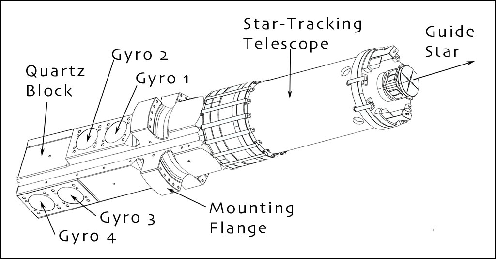
Diagram of the Science Instrument
Assembly (SIA)—the heart of the
experiment
The Science Instrument Assembly
ready for insertion in the probe
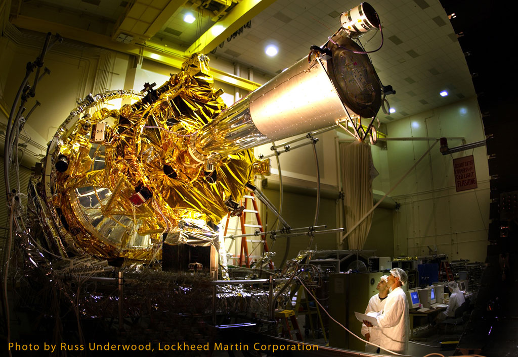
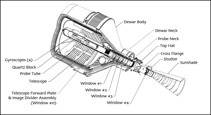
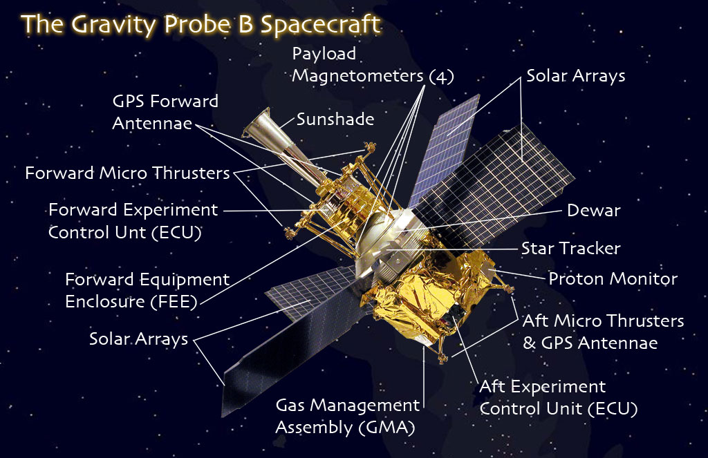
The spacecraft is built around a 650-gallon dewar, one of the largest and most sophisticated ever flown in space. The dewar is nine-feet tall and forms the main structure of the spacecraft. The dewar and its contents comprise the GP-B payload. The illustration to the right shows the dewar’s location in the center of the spacecraft, along with an exploded and labeled view of the main payload components inside the dewar. (Click on the thumbnail to view the illustration at full-size.)
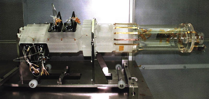
Science Instrument Assembly
The Science Instrument Assembly (SIA) containing the quartz block and telescope forms the pristine spaceborne laboratory for making the measurements of the GP-B experiment. The SIA is located at the center of mass of the spacecraft/dewar, along its main axis. It is mounted inside a cigar-shaped vacuum canister called the Probe (described below).
The quartz block houses the four spherical gyroscopes and SQUID readout instruments (Super Conducting Quantum Interference Devices—the magnetometers that read the gyroscopes’ spin axis orientation). Each spherical gyroscope rotor is enclosed in an elegant, two-piece cylindrical quartz housing, mounted in the quartz block and surrounded by antimagnetic shielding. The gyro rotors are electrically suspended by six round electrode pads—three in the top half of the housings and three in the bottom half—with only 32 microns (~0.001 inch) clearance from these pads, which are embedded in the housing walls. The average spin rate of the gyro rotors during the science phase of the mission was approximately 4,300 rpm.
Bonded to the top of the quartz block using a hydroxide catalyzed optical bonding process, is the quartz reflecting Cassegrain astronomical telescope, which focuses on the guide star, IM Pegasi. Hydroxide catalyzed bonding is a patented method of fusing together quartz parts, without the use of any glue or fasteners to ensure that the SIA did not distort or break when cooled to cryogenic temperatures. The line of sight of the telescope is rigidly aligned to the SQUID readout loop of each gyroscope. As such, the quartz telescope provided the frame of reference for measuring drift in the spin axes of the gyroscopes.
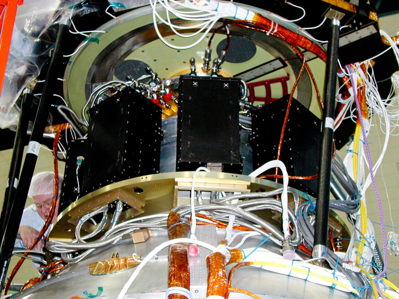
Probe
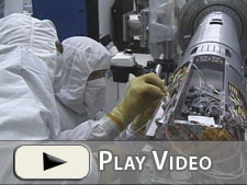
Making repairs to the probe & Science
Instrument Assembly within

Looking into the probe's tophat, where
~450 wires and cables connect with
the science instrument inside
The SIA is mounted in a two-meter long cigar-shaped canister, called the “Probe,” which was inserted into the dewar prior to launch. The Probe is an amazing feat of cryogenic engineering, designed by Lockheed Martin in Palo Alto, California. It provided both mechanical and structural stability for the SIA. The Probe was designed to provide a free optical path for the telescope to view distant space through a series of four precisely manufactured windows, mounted in its upper section. Three of these windows served to reduce thermal conductivity into the dewar, and the fourth, which is made of sapphire, also forms the vacuum seal at the top end of the Probe.
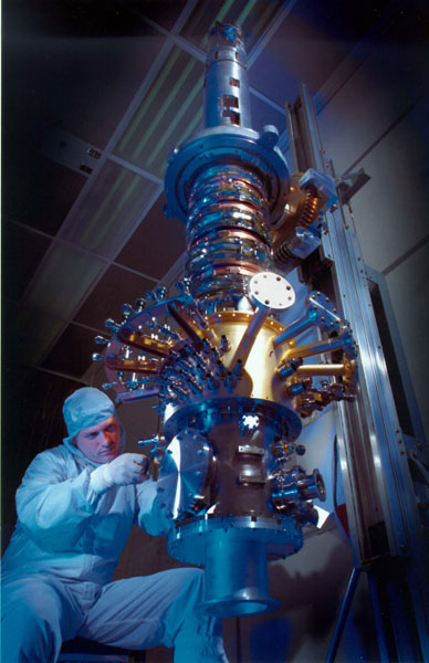
A technician works
on the 9' long probe
During the entire GP-B mission, the inside of the Probe was maintained at an extremely high vacuum—much greater than the vacuum of the thermosphere at the 642 km (400 mi) orbiting altitude of the spacecraft. The probe is surrounded by a superconducting lead bag, inserted between it and the dewar. The superconducting lead bag provided an impenetrable shield from electromagnetic signals that could disturb the gyroscopes. Taken together, all of these measures created an ultra-pristine cryogenic environment, free of any external forces or disturbances, in which the gyroscopes spun during the science phase of the mission.
At the upper end of the Probe, capping off the dewar, is the “top hat.” The top hat served as a thermal interface for connecting over 450 plumbing and electrical lines, that run from various electronics and control systems, mounted on the space vehicle’s truss system outside the dewar, to the cryogenic vacuum chamber inside the Probe and dewar. Before the Probe was completely integrated into the dewar, each component went through years of testing and construction. Some parts even had to be de-constructed and rebuilt. The entire Probe was assembled in a Class- 10 clean room, as any particles larger than a single micron would disrupt the precise structure.
Spacecraft
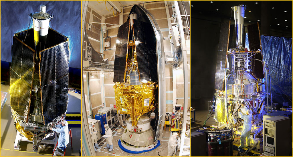
Outside the dewar are all of the systems that provide power, navigation, communication, and control of the space vehicle. The series of CAD drawings below show the location of all spacecraft components from four different side views, plus a top and bottom view. Below and to the right of these CAD drawings is a photograph of a 1/25th scale model of the spacecraft, with labels identifying key system components. The following sub-sections contain brief descriptions of the main components that are mounted on the spacecraft bays, surrounding the dewar.
| Labeled CAD Drawings of the GP-B Spacecraft (Click any thumbnail to enlarge) | |||||
|---|---|---|---|---|---|
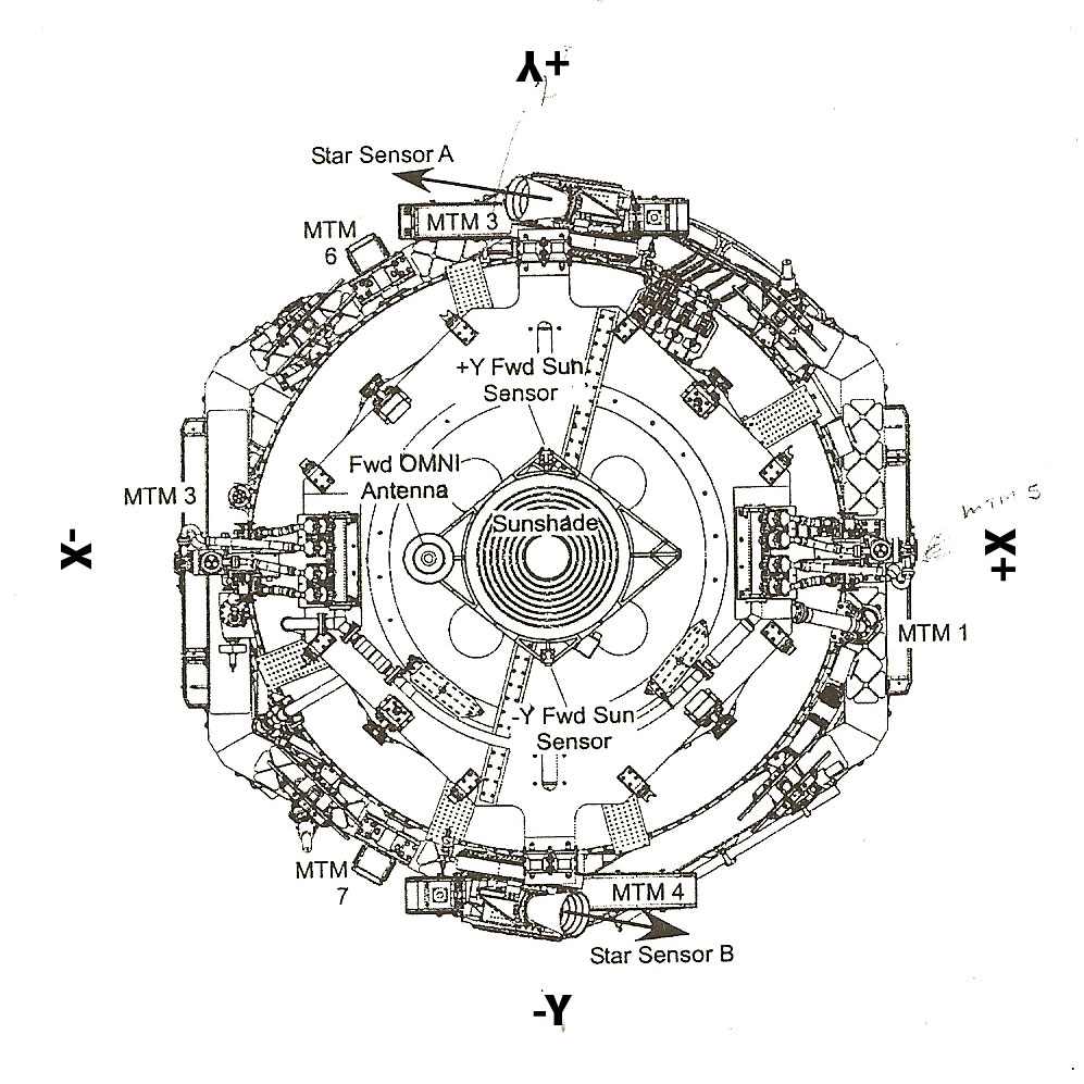 |
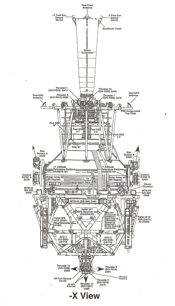 |
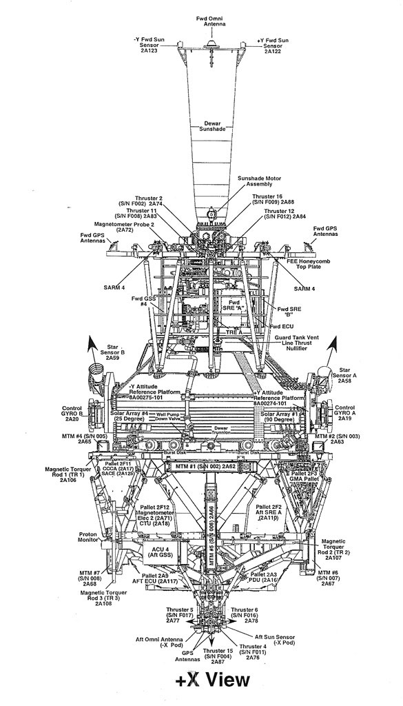 |
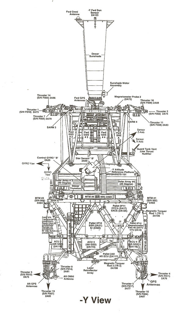 |
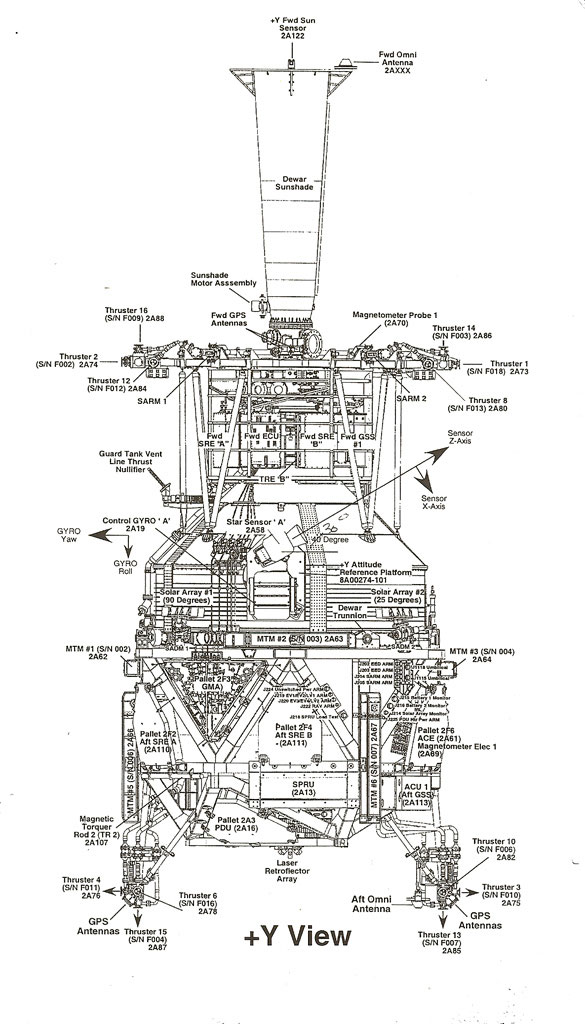 |
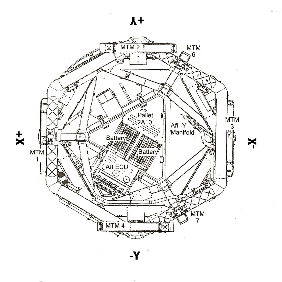 |
| Top View | Side View - X | Side View + X | Side View - Y | Side View + Y | Bottom View |
Control Gyros & Magnetometers
Key spacecraft systems
Three views of the spacecraft
Preparing the spacecraft for launch
GP-B contains two standard, flight-qualified rate-sensing gyroscopes, equivalent to those found on other spacecraft (and also airplanes, ships, and other vehicles). These gyroscopes are part of the general Attitude & Translation Control System (ATC) of the spacecraft, separate from the ultra high-precision sicence gyroscopes inside the dewar and probe. In addition,the ATC system uses data from two magnetometers mounted on the spacecraft frame, as well as GPS sensors, star trackers and magnetic torque rods to control the spacecraft's attitude and position.
GPS Sensors & Antennae
Four GPS (Global Positioning System) antennas on-board the spacecraft—two at the forward end of the spacecraft and two at the aft end—transmit information about the spacecraft’s position and attitude. The GPS system on the GP-B spacecraft provides positioning information that is over 100 times more accurate than traditional ground-based GPS navigation systems. For example, a high quality handheld GPS receiver on Earth can locate your position to within about a meter, whereas the GPS receiver onboard the GP-B space vehicle can locate its position to within a centimeter. (This occurs because the GPS signals used do not have to travel through the Earth’s lower atmosphere.)
Proportional Micro Thrusters
Labeled diagram of the spacecraft
showing the location of the thrusters
16 micro-thrusters used helium gas,
boiled off from the dewar, to control
the spacecraft's position and orientation
Until the helium in the dewar was expended at the end of the mission in late September 2005, the proportional micro thrusters on the spacecraft provided a very precise means of controlling its attitude or orientation in space. For the GP-B experiment, an unprecedented amount of on-orbit control was required for the vehicle to maintain its drag-free flight in orbit. This was accomplished by harnessing the helium gas that continually evaporates from the dewar’s porous plug and venting it as a propellant through eight pairs of opposing or balanced proportional micro thrusters.

CAD drawing of a thruster
cluster (4 thrusters/cluster)
Throughout the mission, these micro thrusters continually metered out a flow of helium gas—at the rate of about 1/100th the amount of a human “puff ” exhalation that one might use to clean eyeglasses. This metered flow of helium kept the space vehicle’s center of mass balanced around one of the gyroscopes, called a “proof mass.” During the flight mission, the spacecraft “chased” the proof mass, thus permitting the proof mass to follow a “free-fall” trajectory without the need for any support force. The thrusters are arranged in pairs, so that they counterbalanced each other. As long as the same amount of helium was flowing from two opposing thrusters, the space vehicle would not change its position relative to the proof mass along that axis. However, if the SQUID readout for the drag-free gyroscope or the telescope readout required the spacecraft’s position or attitude to change, it was simply a matter of unbalancing the flow, ever so slightly, in the appropriate thruster pair to move the vehicle in the desired direction. These proportional micro thrusters also controlled the spacecraft’s roll rate.
Now that the helium is exhausted from the dewar, these micro thrusters are no longer functional. Also, the onboard science telescope has much too narrow a focus to be used for determining the spacecraft’s pointing direction. Instead, two star trackers mounted on the spacecraft frame, along with two magnetometers and standard navigational rate-sensing gyroscopes are used to determine the correct orientation of the spacecraft, and a set of magnetic torque rods are now used to control its attitude by pushing against the local magnetic field of the Earth.
Solar Arrays
Installation of the solar
arrays prior to launch
The GP-B spacecraft features four 3.5 x 1.3 meter (11.5 x 4.25 foot) solar arrays, extending out at 90 degree angles from each other. The four panels are canted (tilted) at seemingly odd angles, which combined with the spacecraft's continuous rolling about its main axis, cause it to resemble a flying windmill (although the canting of the solar arrays was specifically designed to preclude the spacecraft from "windmilling" due to interaction with the solar stream).
These four arrays convert energy from the Sun into electrical power that is stored in the spacecraft’s two batteries and then used to run the various electrical systems on board. The position of each solar array was precisely canted to maximize the power output as the spacecraft rolled and changed position with respect to the Sun over the course of a year. (The orbit plane of the spacecraft always contains the guide star.) See the technology story about the solar arrays and Electrical Power System (EPS) for a more complete description.
Star Trackers
![]()
Conventional star tracker
A star tracker is basically a telescope with a camera and pattern matching system that uses constellations and stars to determine the direction in which a satellite is pointing. The GP-B spacecraft contains two star trackers (also called star sensors) for redundancy. The star trackers have a field of view on the order of eight degrees, and they can focus to a position within 60 arcseconds (0.017 degrees)—about the same as the whole field of view of the on-board telescope, which can pinpoint the guide star’s position to within a milliarcsecond. With such a small field of view, it would be nearly impossible to locate the guide star using only the onboard telescope, so the star trackers functioned like “spotting scopes” for initially pointing the spacecraft towards the guide star. During the mission, once the star tracker had oriented the spacecraft within 60 arcseconds of the guide star, the onboard telescope then took over the job of maintaining the precise alignment required for measuring gyroscope drift.
Sun Shield
The sun shield is a long, conical tube, extending from the top of the probe and dewar, that kept stray light from entering the telescope during the mission. Inside the sun shield are a series of black, metal baffles that absorb incoming stray light before it can reach the telescope. In addition to blocking out stray light from the Sun, the sun shield also blocked stray light from the Earth, Moon, and major planets.
Telemetry and Communications Antennae
These antennae enable both inbound and outbound communications with the space vehicle, including communications with ground stations and with orbiting communications satellites in the Tracking Data Relay Satellite System (TDRSS). Telemetry data from the space vehicle and science data from the experiment are transmitted to ground stations using these communications systems. These systems also enable the GP-B Mission Operations Center (MOC) to send batches of commands to the space vehicle. Communications between the space vehicle and orbiting satellites is limited to a 2K data format, whereas communications with ground stations use a 32K data format, enabling far more data to be transmitted per unit of time.
Electro-Mechanical Control Systems
The GP-B spacecraft includes a number of systems that are partly electrical and partly mechanical and were used to control the spacecraft's position and orientation in orbit, as well as other functions.
Attitude and Translation Control System (ATC)
The Attitude and Translation Control System (ATC) controls the proportional micro thrusters and magnetic torque rods that determine and maintain the spacecraft’s precise position and orientation in orbit. The position, acceleration, attitude and rotation rates of the space vehicle are measured by several redundant sensors. These sensors include both the control and science gyroscopes, star sensors, magnetometers, coarse sun sensors, GPS receivers, and the science telescope. The choice of which set of sensors are used at a given time depends on the selected configuration of the ATC subsystem. Six different configurations were defined for the ATC, two of which were predominately used during the GP-B flight mission. Feedback control logic takes the measured position, acceleration, attitude and rotation rates and computes commands sent to the thrusters and magnetic torque rods in order to maintain the space vehicle in the desired position and attitude.
During the flight mission, the requirements for the Attitude and Translation Control subsystem were twofold:
- The position of the space vehicle must be accurately centered about one of the Science Gyroscopes so that the forces (control efforts) and torques applied to the science gyroscopes are rigorously minimized during the Science Mission.
- The GP-B space vehicle must remain accurately pointed at the Guide Star IM Pegasi, during gyroscope spin up and throughout the Science Mission phase to provide the distant inertial reference and to minimize torques due to mis-pointing.
Once the liquid helium was exhausted from the dewar at the end of September 2005, the micro thruster system became inactive, and the ATC system has since been limited to using the three magnetic torque rods mounted on the spacecraft frame to control the spacecraft's attitude and position.
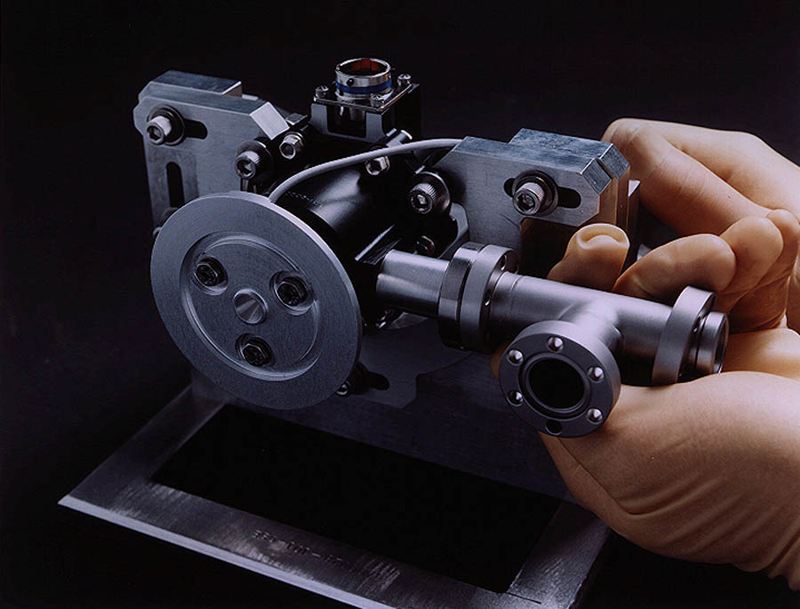
Gas Management Assembly (GMA)

Gas Management Assembly (GMA)
used to spin up the gyros
A very complex set of valves, pipes, and tubing, that runs from a triangular assembly on the spacecraft frame, through the top hat and down the Probe to each of the gyroscopes. The critical job of the GMA is to spin up each of the four gyroscopes by blowing a stream of ultra-pure helium gas over them, through a channel built into one half of each gyroscope’s quartz housing.
The GMA was designed and built for GP-B by Moog, Inc. in Buffalo New York. It has three main operating parts:
- Two high-pressure storage vessels filled with 10.4 liters of helium at 2000psia.
- Two redundant gas manifolds that lead to each gyro inlet, a probe inlet, and a vent path to space. Each gas manifold has two redundant pressure regulators, two flow controllers (725 sccm and 2 sccm), 15 latch valves, and 7 pressure transducers.
- Two heater strips to heat the GMA pallet to 20ºC ±8ºC during valve operations.
During gyro spin-up operations in the IOC phase of the mission, ultra-pure (99.9999%) helium gas was streamed from the GMA down to the gyro housings in the Science Instrument Assembly (SIA) at the bottom of the Probe. As the helium gas descended into the Probe, which was at a temperature of approximately 1.8 Kelvin, the gas cooled down from 273 Kelvin to around 12 Kelvin. Once the gyros had been spun up, all of the helium gas molecules remaining in the probe had to be evacuated through a set of exhaust valves and by a procedure called "low temperature bakeout." During this procedure, the interior of the probe was heated by 5-7 Kelvin to release the last remaining helium molecules, which were released into space and/or adsorbed by a device in the probe neck called a "cryopump." You can read about the low temperature bakeout procedure in our Mission Status Update of August 6, 2004.
Magnetic Torquing System (MTS)
Torque rods are essentially electromagnets, mounted on the spacecraft's frame, that interact with the Earth's magnetic field to place a controlled force, or torque, on the spacecraft, thus changing its orientation. The torque rods on the GP-B spacecraft were manufactured by Ithaco, a division of Goodrich. Each of these rods is 91 cm (35.8 in) long and 3 cm (1.2 in) in diameter. Each rod is made of iron and wound with thin copper wire to form an electromagnet. For redundancy, each rod is actually wound with two long strands of wire, and each coil is powered separately.
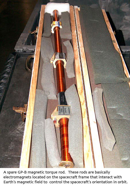
Magnetic torque rod
Three torque rods are mounted on the base of the spacecraft's frame, each in a position corresponding to one of the spacecraft's three axes, X, Y, or Z. Thus, the orientation of each rod is orthogonal to that of the other two. When current is passed through the coil of a torque rod, the rod becomes an electromagnet, and the strength of the magnetic field generated is a function of the amount of current flowing through the coil. Also, the direction of the current flow determines whether the torque rod generates a repelling or attractive force with respect to the Earth's magnetic field.
Because of their orthogonal positioning, the three rods generate controlled torques along all three axes, enabling the Attitude & Translation Control System (ATC) to control the spacecraft's pitch, yaw, and roll. A torque exerted on the spacecraft by any of the rods reaches a maximum when the rod is oriented orthogonal to the Earth's magnetic field lines and decreases to zero when the rod is directly aligned with Earth's magnetic field. Thus, whenever two of the rods are oriented orthogonal to Earth's magnetic field lines, the third rod will generate no torque.
During the GP-B flight mission, the magnetic torque rods were used in conjunction with 16 proportional micro thrusters to control the spacecraft’s pointing with extreme precision. Following the mission, with no helium propellant remaining to operate the micro thrusters, these magnetic torque rods are the only means of controlling the spacecraft’s attitude and position in orbit.
Mass Trim Mechanism (MTM)
Mass Trim Mechanism (MTM)
The GP-B spacecraft includes three movable “mass trim,” weights, mounted on long screw shafts in strategic locations on the spacecraft frame. Small motors, under control of the spacecraft’s ATC, can turn these screw shafts in either direction, causing the weights to move back and forth by a specified amount. Thus, based on feedback from the GSS, the spacecraft’s center of mass can be precisely centered, both forward to back, and side to side, around the designated “drag-free gyro.” The process of adjusting the mass trim weights on the spacecraft is similar in concept to spin-balancing an automobile tire.
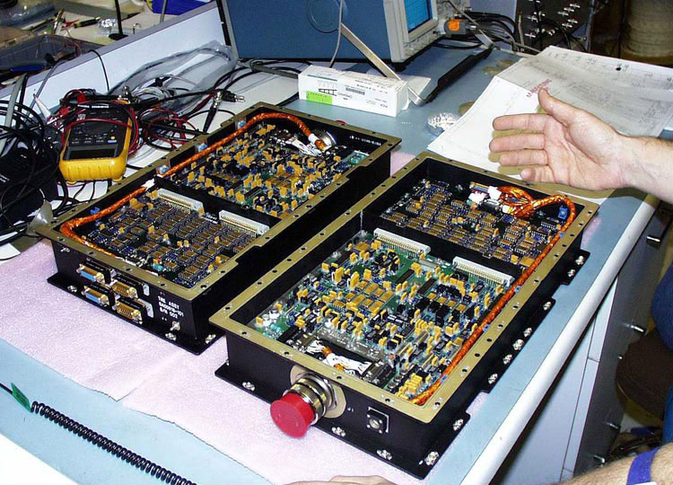
Computers & Electronic Systems
In addition to the main spacecraft components and electro-mechanical control systems, the spacecraft frame also houses the computers and related electronics boxes that control and/or communicate with critical systems both for the spacecraft and elements of the payload, inside the dewar.
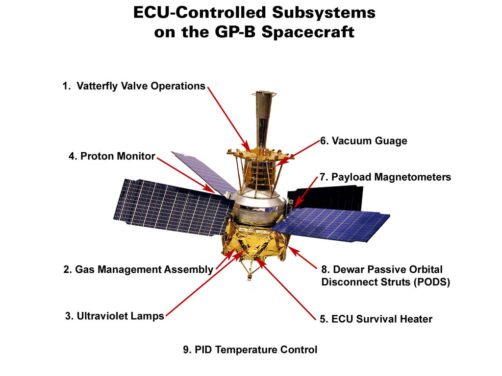
Experiment Control Unit (ECU)
The ECU actually comprises two electronics boxes, one inside the Forward Equipment Enclosure (FEE) located above the neck of the dewar and the other located in one of the bays that surround the bottom of the dewar. The ECU controls a number of heaters and temperature sensors inside the dewar and inside the Probe. In addition, the two ECU boxes control the following nine subsystems both inside and outside the dewar, as shown in the lower diagram to the right. (Click on the thumbnail to view the diagram at full size.)
Following are brief descriptions of these nine subsystems:
- Vatterfly Valve Operations—There are 6 Vatterfly Valves operated by the ECU. Two (2) 6-inch Leakage Valves, used for exhaust from the top of the dewar. Four (4) 2.5-inch Exhaust Valves, used for exhaust from each Gyro and plumbed up and out near the top of the dewar.
- Gas Management Assembly (GMA)—The ECU provides heater control, temperature monitoring, and valve control for the GMA, which is described above.
- Ultraviolet Lamps—The ECU operates two UV lamps and their optical switches. These UV lamps are used for controlling the buildup of electrostatic charge on the science gyros.
- Proton Monitor—The Proton Monitor is a modifiable system designed to monitor the GP-B’s environment and detect and distinguish in between protons, electrons and other charged particles/cosmic rays.
- ECU Survival Heater—Designed to maintain the Aft ECU Operational Temperature Range, the Aft ECU baseplate survival heater protects the UV Lamps from low temperature damage. They thermostatically maintain a temperature in between 0 and 4 Celsius.
- Vacuum Gauge—The ECU provides +30V, 3W max. power and 2 channels of telemetry for each of two high vacuum gauges., used to measure probe pressure during high probe pressure events.
- Payload Magnetometers—The ECU houses control circuitry for four external 3-axis magnetometers, and it provides three channels of analog telemetry.
- Dewar Passive Orbital Disconnect Struts—The ECU senses the status of the dewar Passive Orbital Disconnect Struts (PODS), which are used to thermally isolate the dewar from the spacecraft structure surrounding it.
- PID Temperature Control—The spacecraft’s main computers (CCCA and backup CCCB) use a closed loop temperature control (PID) algorithm to control a number of heaters located in various places inside the dewar and probe, including: Gas Inlets (Final Filters, two sets), Quartz Block Structure (QBS),. Cryopump, Vacuum Shell, and heaters for each of the four windows in the Probe.

Locations of the fore and aft ECU boxes
Subsystems controlled by the ECU
Flight Computers—Main (CCCA) & Backup (CCCB)
The main flight computer and its twin backup are called the CCCA (Command & Control Computer Assembly). These computers were assembled for GP-B by the Southwest Research Institute. They use approximately 10-year old IBM RS6000 Central Processing Units (CPUs), with 4 MB of radiation-hardened RAM memory. These computers, along with ruggedized power supplies are encased in sturdy aluminum boxes, with sides up to 1/4” thick.
Gyro Suspension System (GSS)
Four GSS control modules mounted
on the spacecraft frame
As noted in the Extraordinary Technologies—World's Most Perfect Gyroscopes section, the GSS electronics control the levitation and positioning of the four science gyroscope rotors. Each gyroscope has a dedicated GSS system, and each GSS system comprises two electronics enclosures: forward and aft. The forward electronics unit (FSU) resides in the spacecraft’s forward equipment enclosure (FEE), that is passively thermally controlled to a range of 300-320K over the mission. The FSU contains the sensitive analog electronics that are used to sense the position of the rotor and apply suspension voltages.The forward unit communicates with the aft unit via a pair of unidirectional parallel data busses, one aft-toforward and one forward-to-aft. Timing signals, including the 34.1 kHz bridge excitation signal are provided via this link. The GSS aft control unit (ACU) houses the GSS flight processor card, associated support circuitry, and the power supply for the GSS string. This unit is mounted on the aft truss of the spacecraft, and thus is subject to wider temperature swings, approximately 265K to 300K.
Each GSS employs a dedicated Lockheed-Martin Federal Systems (now BAE) RAD6000 processor, running at 16.368 MHz. On board is 1 MB of EEPROM and 3 MB of static RAM. The processor communicates with the spacecraft via a Mil-Std-1553 serial link and with the GSS electronics via a parallel port on the processor card. This processor holds the gyro suspension system software and telemetry processing needed to receive commands and send measurements to the ground via the spacecraft processor (CCCA). The telemetry system continuously provides data at 2 to 5 second intervals of gyro position, control effort, suspension voltages applied, system state, analog monitor points, box temperatures, and other engineering information. Also available are high-speed snapshots consisting of 12 seconds of full rate suspension control loop measurements and commands.
SQUID Readout Electronics (SRE)
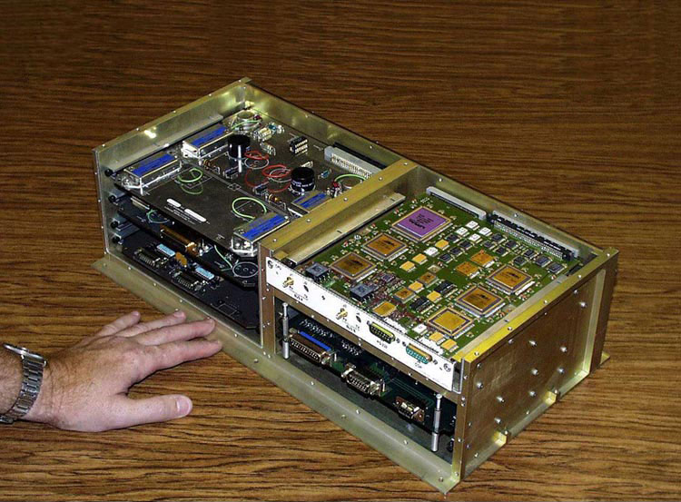
One of the SQUID Readout Electronics
(SRE) computers
During the science phase of the mission, as described in the Extraordinary Technologies—Gyro Readout System, the SRE electronics were responsible for providing ultra-precise data on the orientation of the spin axis of each of the four gyroscopes. The payload electronics includes two SREs located in the Forward Equipment Enclosure (FEE) in order to provide readout system redundancy and ensure overall reliability. Both forward units are operated simultaneously. FWD SRE A controls the SQUIDs for gyroscopes 1 and 3 and the SQUID bracket temperature control for SQUIDs 1 and 2, while FWD SRE B controls the SQUIDs for gyroscopes 2 and 4 and the SQUID bracket temperature control for SQUIDs 3 and 4. The sub-blocks located with the FWD SRE include: FLL = Flux locked Loop electronics, DAC = Digital to Analog conversion electronics, DAS = Data Acquisition System and BTC = Bracket (SQUID) Temperature Control electronics as well as power management, auxiliary analog test ports and communications blocks. The SRE subsystem also provides power, digital communications and digital processing for the Telescope Readout Electronics (TRE).
The payload electronics also includes two AFT SREs (A and B) in order to provide readout system redundancy and ensure overall reliability. At most one AFT SRE is operated at any one time. The AFT SREs manage power and communications for the forward SRE/TRE units. They also contain a payload processor running software particular to the SRE/TRE and an oven controlled crystal oscillator (OCXO), which provides a single accurate timing to all the payload electronics.
Solid State Recorder (SSR)
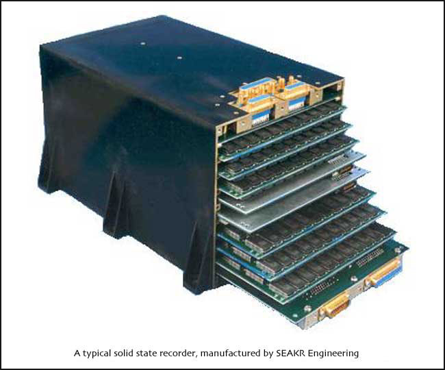
A typical solid state rcorder
An SSR is basically a bank of Random Access Memory (RAM) boards, used on-board spacecraft to collect and store data. It is typically a stand-alone “black box,” containing multiple memory boards and controlling electronics that provides management of data, fault tolerance, and error detection and correction. The SSR onboard the GP-B spacecraft has approximately 185 MB of memory—enough to hold about 15.33 hours of spacecraft data. This is not enough memory to hold all of the data generated by the various monitors, so the GP-B Mission Operations staff controlled what data were collected at any given time, through commands sent to the spacecraft.Many instruments on-board the spacecraft have their own memory banks. Data rates from these instruments vary—most send data every 0.1 second, but some are faster and others slower. The data from all of these instruments are collected by the primary data bus (communication path) and sent to the central computer, called the CCCA. You can read more about the SSR in the Data Collection, Processing & Analysis section of the Mission tab.
Telescope Readout Electronics (TRE)
The TRE electronics boxes process the signals generated by the telescope detector packages, as described in the Extraordinary Technologies—Telescope & Guide Star section. The telescope readout electronics measures the light reflected from each side of the roof prisms. The light from the two sides of a roof prism is transported to two pairs of photo detectors, a primary pair (A-side electronics) and a redundant pair (B-side electronics). Each photodetector pair is located on a sapphire platform with their JFET pre-amplifiers. The platforms are mounted on a thermal standoff on the front plate of the telescope (at about 3 K) so the platforms can be operated at 72 K, where the JFET pre-amplifiers work well. The platforms are temperature controlled. There are a total of 4 detector pairs (8 detectors) located on 4 platforms.
Telescope Readout Electronics (TRE)
computers
The TRE measures the current of each photo detector with a charge-locked loop using a feedback capacitor to the photo detector. The voltage across the feedback capacitor is read out after appropriate scaling by an analog-to-digital converter with a range from +10 V to -10 V at a rate of 2200 samples/second, and it is quickly reset every 0.1 s. This provides 220 A-to-D samples for each charge ramp. Only the even samples between 22 and 220 of the ramp are used to determine the science slope (photo detector current after appropriate scaling). The first few samples are ignored to avoid the transient associated with the reset, and only the even samples are used to reduce the on-orbit computation time for the slope. Little information is lost in using only the even samples since adjacent samples have a moderate degree of correlation.
Portions of the SQUID Readout Electronics (SRE) provide power and control information to the TRE, as well as digital-to-analog conversion, data handling, and signal processing for the TRE output signals. The four channels of the TRE are very independent of each other, with four identical sets of circuit boards that are housed in two boxes in intimate contact with a corresponding SRE forward unit. There are two identical aft SRE units, but one is always powered off while the other is active.
Full Realization of a Drag-Free Satellite
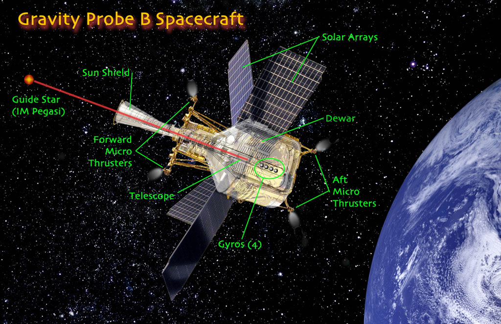
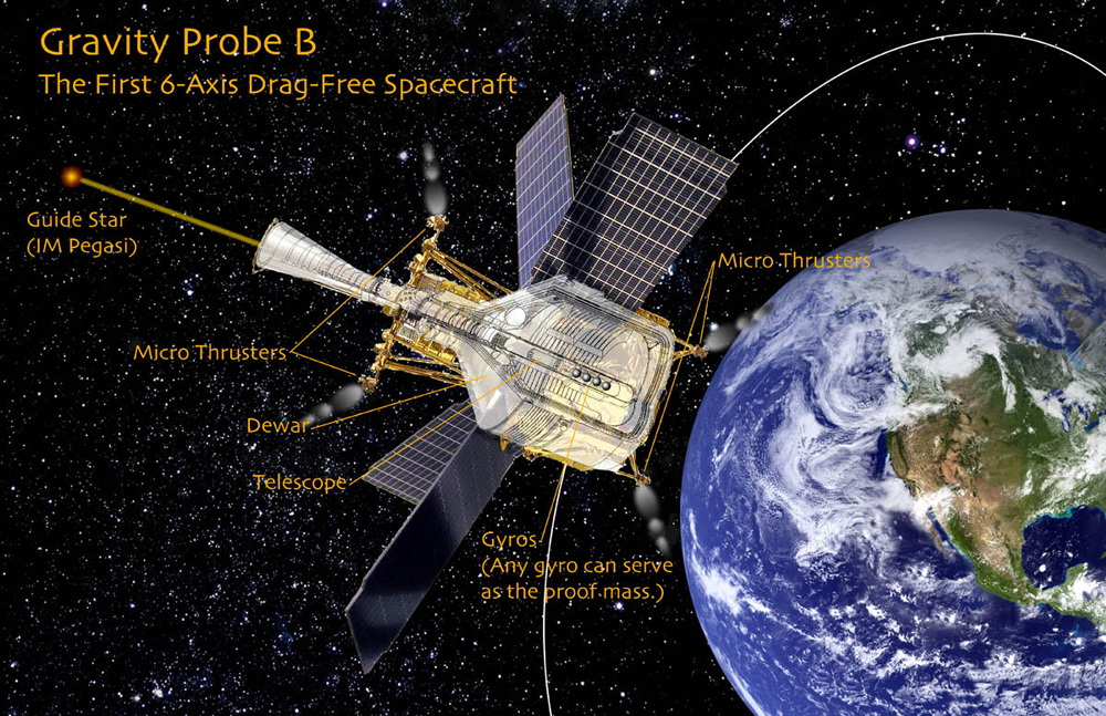
Gravity Probe B is the first spacecraft ever launched requiring six degrees of freedom in active attitude control— three degrees of freedom in pointing control to maintain its guide star pointing orientation and constant roll rate (pitch, yaw, and roll) and three degrees of freedom in translational control (up-down, front-to-back, and side-to-side), to maintain a drag-free orbit throughout the 17-month flight mission.
GP-B is the second fully drag-free
satellite ever flown
How a drag-free satellite works
The term “drag-free” refers to a body that is moving without any friction or drag, and thus its motion is affected only by gravity. Here on Earth, and even 642 km (400 miles) above the Earth where the GP-B satellite is in orbit, there is always some drag caused by the Earth's atmosphere, solar pressure, and other forces. However, a body can achieve drag-free motion if it is shielded by another body. A drag-free satellite, therefore, refers to a feedback system consisting of a satellite within a satellite. The inner satellite, often called a proof-mass, is typically a small homogeneous object, such as a spherical GP-B gyroscope. The position of the outer shielding satellite must be tightly controlled to prevent it from ever touching the proof mass. This is accomplished by equipping the outer satellite with sensors that precisely measure its position relative to the proof mass and a set of thrusters that automatically control its position, based on feedback from the sensors. Through this feedback system, the satellite continually “chases” the proof-mass, always adjusting its position so that the satellite remains centered about the proof mass, which is orbiting the Earth in a constant state of free fall. The drag-free feature of the GP-B spacecraft is critically important to the experiment because orbital drag on the spacecraft would cause an acceleration that might obscure the minuscule relativistic gyro precessions being measured.
GP-B needs extremely sensitive thrusters to re-orient the satellite and keep it on its proper path. Here's where the escaping helium gas that slowly boils off from the liquid helium comes in handy. Minute amounts of gas, 1/10th of a human breath or a few millinewtons of force, provide just the right amount of thrust necessary to adjust the satellite's position.The first, and only other 3-axis drag-free controller ever flown was called DISCOS (DISturbance COmpensation System). It was developed in the late 1960s as an offshoot of GP-B under the leadership of Professor Dan DeBra, then head of the Guidance & Control Laboratory in the Stanford Aero-Astro Department, and a Co-Principal Investigator on GP-B.
DISCOS was the central drag-free control module in the three-module TRIAD I satellite, a test vehicle developed to improve the accuracy of the U. S. Navy’s Transit satellite navigation system. Transit satellites enable ships to locate their positions on the Earth's surface by reference to orbit data stored on board the satellite, but earlier ones had been limited by uncertainties in orbit prediction arising from atmospheric drag. The DISCOS module was specifically designed to address this problem. The other two modules in the TRIAD I satellite were developed by the Applied Physics Laboratory (APL) at Johns Hopkins University, under the leadership of Robert Fischell. The TRIAD I satellite, with its central DISCOS module, was launched on September 2, 1972 and flew in a polar orbit at 750 km for a little more than a year and achieved drag-free performance of 5x10-12 g for the entire mission. Subsequently, the Navy built two more satellites in the TRIAD series, followed by three satellites in the NOVA series. All of these subsequent satellites contained only singleaxis drag-free control, the development of which also included significant contributions by Stanford faculty and graduate students.
See also, the GP-B History & Management—Early Research & Development section in the Mission tab.
Learn more about drag-free satellites:
- View a PDF of George Pugh's 1959 memo entitled, Satellite Test of the Coriolis Prediction of General Relativity,in which the concept of a drag-free satellite was first proposed.
- View a PDF transcript of the complete presentations and discussions from the 1961 NASA relativity experiments conference.
- View a PDF of Cannon, Fairbank & Schiff's Proposal to Develop a Zero-G, Drag-Free Satellite and to Perform a Gyro Test of General Relativity in a Satellite, submitted to NASA in November 1962.
- View a PDF of Benjamin Lange's 1964 Stanford doctoral dissertation, entitled: The Control and Use of Drag-Free Satellites.
- View a PDF of Benjamin Lange's 1964 paper entitled, The Drag-Free Satellite, from the American Institute of Aeronautics & Astronautics Journal (AIAA), Volume 2, Number 9, Septermber 1964, pp. 1590-1606.
- View a PDF of Daniel DeBra's 1974 paper entitled: A Satellite Freed of All But Gravitational Forces: "TRIAD I", from the American Institute of Aeronautics & Astronautics Journal (AIAA), Volume 11, Number 9, September 1974, pp. 637-644.
Redundancy in Systems & Technology
Underlying the entire GP-B experiment is a philosophy of redundancy that has been built into the GP-B spacecraft and all of its subsystems. Following is a description of this redundancy.
Gyroscope Redundancy
At the highest level of the GP-B experiment, redundancy begins with the four gyroscopes. We actually need only one gyroscope to perform the GP-B experiment, but since it is unlikely that this experiment will ever be repeated, it seemed prudent to build redundancy into the experiment itself. Having four gyros obviously provides backup in case one, two, or even three gyros should fail during the mission. More important, however, having multiple gyroscopes provides built-in crosschecks on the relativity data. In other words, a high degree of correlation in data collected from four independent gyros provides greater confidence in the results than data collected from a single gyro, or even two gyros—especially if the results should differ from the predictions of general relativity.
Gyro Suspension System Redundancy
An independent Gyro Suspension System (GSS) computer controls each of the gyros. Each GSS computer is connected to a single gyro, so they cannot be used interchangeably. Each of the GSS computers has two gyro suspension modes—analog and digital—that provide a form of redundancy in the gyro rotor suspension. The analog suspension mode is used primarily as a backup or safe mode for suspending the gyros. The digital suspension mode is computer-controlled; it puts less torque on the gyros than analog mode and enables their position to be controlled with extremely high precision. A failsafe mechanism, called the arbiter, is hard-coded into the GSS firmware (programming at the chip level) that automatically switches the suspension system from digital to analog mode under certain pre-set conditions.
Computer Redundancy
The GSS computers comprise four of the eight computers on-board the spacecraft. In addition there are two flight computers and two SQUID Readout (SRE) computers. The main flight computer and its twin backup are called the A-Side (main) and B-Side (backup) CCCA (Command & Control Computer Assembly). Only one of these computers is running at any given time. If the A-side computer fails certain safemode tests, the B-side computer automatically takes over, as was the case in March 2005. However, when the backup computer failed these safemode tests, it was rebooted. We can only switch back to the main computer through manual commands.
SQUID Readout Redundancy
Each of the twin SRE computers can control all four SQUID readouts, showing the spin axis orientations of all four gyros. Like the main computers, only one of the SRE computers is running at any given time. When the main CCCA computer automatically switched over to the B-side in March 2005, the SRE computer did not switch with it. However, in order to synchronize the timing between the B-side CCCA computer and the A-side SRE computer, we commanded the SRE computer to reboot. Also, to ensure that we remained on the A-side SRE computer, we disabled the safemode response that automatically switches from the A-side SRE computer to the B-side SRE computer.
Telescope Readout Redundancy
Redundancy is also built into the Telescope Readout Electronics (TRE). The science telescope has two sets of detectors, designated A-side (primary) and B-side (backup). These detector packages, which are about the diameter of a dime, are comprised of pairs of silicon photo diodes that basically count photons from each half of the telescope's split beam, in both the X-axis (side-to-side) direction and the Y-axis (top-to-bottom) direction. Beam splitters and mirrors are used to redundantly direct all of these split light beams to the B-side detectors as well as the A-side detectors. For comparison sake, we collected the data from both the primary and backup detectors during telemetry communications passes, although we only used the data from one set of detectors to control the spacecraft's pointing direction through the ATC system.
Attitude Control System Redundancy
The ATC uses the navigation control gyros (called “rate” gyros), star trackers, and magnetometers to control the spacecraft's attitude when the telescope detectors are not controlling the spacecraft's attitude (e.g., the portion of each orbit when the spacecraft moves behind the Earth, eclipsed from view of the guide star). The spacecraft contains two pairs of rate gyros, two star trackers, again designated A-side (primary) and B-side (backup), and two navigational magnetometers. The two rate gyros in each pair work together, independently controlling the X-axis and Y-axis position of the spacecraft; the redundant Z-axis position control from one of the gyros is not used. The star trackers are essentially pattern-matching cameras, located on opposite sides of the spacecraft frame. The payload magnetometers are like three-dimensional compasses that determine the spacecraft’s orientation with respect to the Earth’s magnetic field.
During the 17-month GP-B flight mission, all of the above systems, in addition to data from the Gyro Suspension Systems were used to “steer” the spacecraft in its orbit. Moment to moment changes in the spacecraft’s position were controlled by a combination of 16 micro thrusters (see below) and a set of magnetic torque rods—long electromagnets that push or pull against the Earth’s magnetic field to change the spacecraft’s orientation. After the helium was depleted from the dewar at the end of September 2005, these torque rods, controlled by feedback from the star trackers and magnetometers, are the only means of re-orienting the spacecraft in the post-mission phase.
Star Tracker Redundancy
Both star trackers were turned on and have been running since the beginning of the mission, but only one pair of rate gyros was in use. During the science phase of the mission, we activated the other set of rate gyros, as well. Data from one set was sent to the ATC to control the spacecraft's position; data from the other set was collected during telemetry communications sessions and used for precise roll attitude calibrations to the science data. The B-side switch-over of the CCCA computer in March 2005 also triggered a switch to the B-side rate gyros and star tracker. We subsequently commanded the spacecraft to switch back to the A-side rate gyros and the A-side star tracker, both of which had been fine-tuned during the Initialization and Orbit Checkout (IOC) phase of the mission and were performing slightly better than their backup counterparts.
Micro Thruster Redundancy
The final redundant spacecraft system is the micro-thruster system. The spacecraft is outfitted with 8 pair of opposing micro-thrusters, arranged in four clusters—two at the top of the spacecraft frame and two at the bottom. One thruster in each cluster is redundant, and a set of valves in the thruster system enables individual thrusters to be isolated and effectively disabled. This is precisely what we did early in the mission with two micro-thrusters, whose nozzles became stuck open, apparently due to particle contamination shortly after launch. The remaining 14 thrusters performed flawlessly throughout the science and post-science instrument calibration phases of the mission.
<- Extraordinary Technologies (Previous) | Unique Challenges & Solutions (Next) ->