Unique Technology Challenges & Solutions
On this page:
- The Porous Plug
- Nested Lead Bags
- Proportional Micro Thrusters
- Polishing the Perfect Sphere
- Measuring Perfect Sphericity
- Suspending the Gyroscopes
- Managing Helium Gas
- Inside the Telescope
- Gyro Readout: Marking the Unmarkable
- The Solar Arrays
- A Heat-Absorbing, Hermetically Sealed Window
- Precision Pointing
When the GP-B experiment was conceived late in 1959-1960, much of the technology had not yet been invented to accomplish this exacting test. Here are the some of GP-B�s unique technology inventions and clever solutions to difficult challenges.
Porous Plug: A Stanford University/GP-B Invention
Challenge: On Earth, dewars (Thermos bottles) function because of gravity. The liquid and gas naturally separate. In the zero gravity of space, a different method of separation is needed.
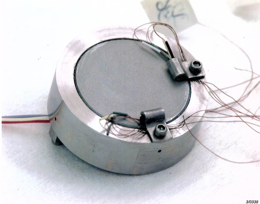
The porous plug
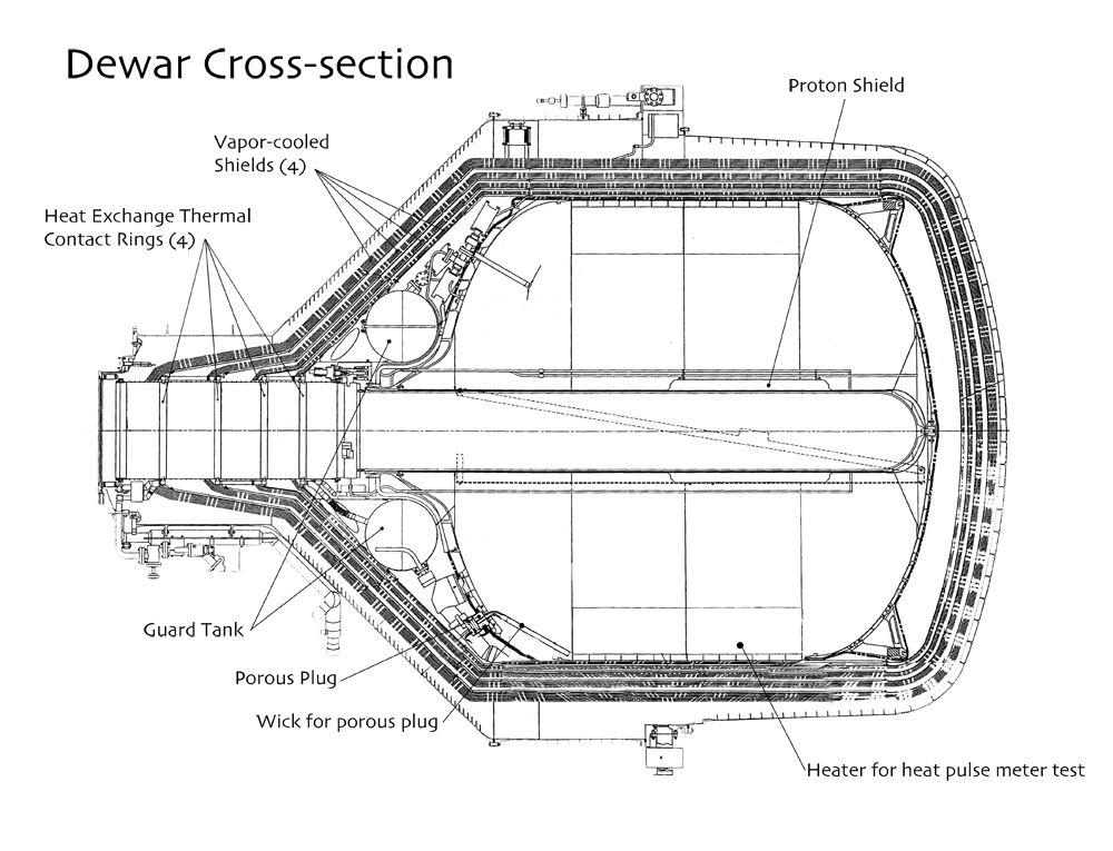
dewar cross-section
Solution: Release the evaporating helium while retaining the superfluid liquid helium. Superfluidity is a characteristic of liquid helium that appears only when it is 2.18 kelvin or colder (during the mission, the temperature of the liquid helium in the dewar was held at 1.8K). When liquid helium is superfluid, it has no viscosity. This allows it to move about on a surface or through a porous substance without friction. A remarkable effect of this state is that if superfluid helium is left in an open beaker in a supercooled environment, the liquid will crawl up the inside of the beaker and down the outside until the beaker was empty!
The role of the porous plug was to control this flow of superfluid helium just enough to let some of it evaporate without letting the liquid leak out. A simple vent would not work because in a zero-g environment, the superfluid helium would simply migrate out of any opening in the dewar, no matter how small we made it or how quickly we opened and closed it. Instead, we needed to make a porous plug.
The plug itself is made of stainless steel, but it has gone through a sintering process that makes it slightly porous (like a sponge). Sintering is a process of powdering a material into tiny granules and then heating the granules until they coalesce into a porous mass, without heating them so high that they melt together. The pores in the resulting mass are extremely small (in fact, invisible to the naked eye), but they are large enough for the superfluid helium to find its way through the plug.
Before the oozing superfluid helium leaks completely through the plug, it reaches a point where it begins to evaporate (called the liquid-vapor interface). When it evaporates, the helium vapor takes heat energy out of the liquid helium. Now the liquid helium near the outside of the plug is colder and it sinks back into the dewar. At least, this is how it was supposed to work.
Choosing the right size for the porous plug was tricky. If the plug had been made too small, the liquid-vapor interface would have remained below it, choking the plug and preventing the release of helium vapor. If the plug had been made too large, the interface would have been above it, and the liquid helium would have oozed out of the plug before it had evaporated and would been lost. The proper size turned out to be a 6.9 cm disk, 0.635 cm thick with a permeability of 3.8 x 10⁻¹⁰ cm squared. The material for the plug is a low-carbon version of stainless steel provided by the Mott Corporation in Connecticut (which also produced our sintered titanium filters to purify the helium gas and the sintered titanium blades for the cryopump).
Result: By using the porous plug, we were able to maintain a steady pressure and temperature inside the dewar. The liquid helium stayed within a few millikelvin of 1.8K throughout the mission. In turn, this allowed the science instrument to operate properly at superconducting temperatures and enabled us to collect 11.5 months of relativity data to test Einstein.
Historical Note: The porous plug was developed at Stanford specifically for the GP-B experiment, but it flew on both the NASA IRAS (Infrared Astronomical Satellite) and COBE (Cosmic Background Explorer) spacecraft prior to the launch of GP-B.
Nested Expanding Lead Bags
Challenge: Earth's magnetic field interferes with the hyper-sensitive magnetometer (SQUID), which reads each gyroscope's orientation to within 0.5 milliarcseconds (1.4x10⁻⁷ degrees).
Lead bag magnetic shield in GP-B flight probe
Solution: Block out the ambient magnetic field by surrounding the science instrument with a "lead bag." Four lead bags are actually used. The first one is inserted and expanded, partially reducing the magnetic field (by the ratio of final to initial volume.) Another bag is then inserted inside the first one and expanded, further reducing the magnetic field inside the second bag. The outer bag is then cut away. This process is repeated two more times, all but eliminating the magnetic field within the innermost bag. At this point the Probe, containing the gyroscopes and SQUIDS is inserted inside the final remaining lead bag.
Result: The series of four nested and expanded lead bags reduces the magnetic level to less than 10-6 gauss. Then, magnetic shields surrounding each individual gyroscope and other local magnetic shields attenuate the magnetic variation down to 10-14 gauss.
Proportional Micro Thrusters
Challenge: GP-B satellite's path is altered, ever so slightly, by solar radiation and atmospheric "wavetops".
GP-B proportional micro thruster assembly
Solution: Re-orient the satellite with an extremely sensitive gas thruster system. Helium gas constantly flows out of eight pairs of opposing thrusters in balanced amounts. To alter the satellite's attitude, the gas flow in one or more pairs of opposing thrusters is unbalanced by 1/100th of a "puff" exhalation that one might use to clean eyeglasses, providing just a few millinewtons of force.
Result: These proportional micro thrusters precisely maintain the GP-B space vehicle's position to within 10 milliarcseconds (3x10⁻⁶ degrees) of a perfect Earth orbit, and pointing to within 1 milliarcsecond (3x10⁻⁷ degrees) of the exact center of the guide star.
Bonus Fact: This is the ultimate in recycling! The helium gas that continually evaporates through the porous plug from the superfluid liquid helium inside the dewar, is harnessed as the propellant used by the proportional micro thrusters.
Polishing the Perfect Sphere
Challenge: Polishing a fused quartz sphere with standard methods creates "hills and valleys," destroying sphericity.
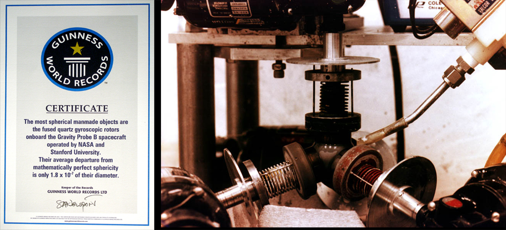
Polishing a gyro rotor
Solution: Create a tetrahedral lapping and polishing machine that brushes the sphere with micro-inch abrasive slurry in random variations.
Result: Each fused quartz sphere deviates less than one micro-inch from peak to valley (25 nm), making them the roundest objects ever created on Earth.
Bonus Fact: In September 2004, GP-B received a certificate from Guinness World Records Limited, acknowledging that the GP-B gyroscope rotors had been entered into the Guinness Database of World Records. The certificate reads as follows:
"The most spherical man-made objects are the fused quartz gyroscopic rotors onboard the Gravity Probe B Spacecraft operated by NASA and Stanford University. Their average departure from mathematically perfect sphericity is only 1.8 x 10⁻⁷ of their diameter."
Precisely Measuring Sphericity (Roundness)
Challenge: How to measure the roundness of a sphere at the precision level of 1/10th of one millionth of an inch? The British instrument company, Rank, Taylor, and Hobson, created the Talyrond instrument for measuring the sphericity or roundness of GP-B gyroscope rotors using a stylus mounted on a round spindle to encircle a gyroscope rotor. However, they could not produce a spindle that was itself perfectly round, and thus the spindle introduced error into the measurement.

Measuring the roundness of a gyro rotor and mapping the contours on its surface
Solution: Combine the errors in the spindle's roundness with the errors in the sphere being measured. Then, rotate the sphere to a new position and repeat the measurement.
The measurement errors in the roundness of the spindle remain constant, while the measurement errors in the sphere change with each new position. After repeating this process several times, it is possible to separate out the constant spindle error. (The spindle roundness must be checked from time to time, to ensure that it has not changed.)
Result: The spindle roundness errors were calculated and stored in a computer, so they could be reused with different spheres. For each rotor, 16 great-circle measurements were made in the perpendicular plane and one final measurement was made around its equator, tying all the vertical measurements together. The spindle errors were subtracted out of the sphericity measurements, and then the sphericity measurements were translated into contour maps.
Gyroscope Suspension System
Challenge: Suspend each spinning gyroscope in the exact center of its housing, a mere 32 microns or 1/1000th inch from the side of the housing.
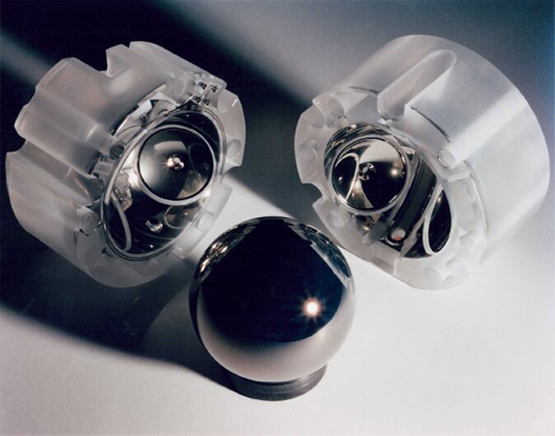
A gyro rotor and both halves of its quartz housing
Constraint 1: The suspension mechanism must be able to react instantly to misalignments, without overreacting and sending the gyroscope crashing into the side.
Constraint 2: The gyroscopes must maintain a spin rate greater than 3,500 rpm.
Solution: Six electrodes placed evenly around the gyroscope create a charge that electrically suspends the gyroscope. The charge attracts the gyroscope's niobium surface. Using a few millivolts, the gyroscopes are constantly balanced in the center of the housing with every electrode reacting dynamically to any adjustments by the other electrodes.
Bonus Fact: While in space it takes less than 100 millivolts to suspend the gyroscopes, whereas on Earth it takes nearly 1,000 volts to raise and balance the gyroscopes against the force of gravity.
Gas Management Assembly
Challenge: Spin up an ultra-smooth gyroscope as fast as possible without crashing it into the sides of the housing with an electrical spark.
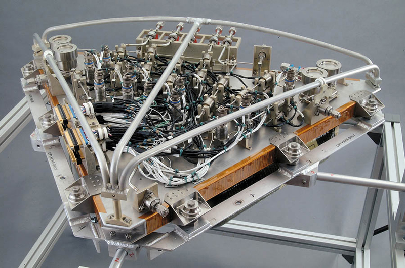
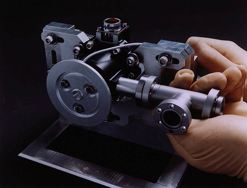
Top view of the Gas Management Assembly (GMA)
Constraint 1: Gas flowing into housing chamber can exit only as fast as the exhaust tube will allow.
Constraint 2: The exhaust tube must be very small (< 1/16th of an inch) to prevent outside heat from reaching the housing chamber and the gyroscope.
Constraint 3: If more gas flows into the chamber than flows out, the pressure inside the chamber will rise. As the pressure rises, the helium will ionize and possibly arc. The electrical spark could knock the electrically suspended gyroscope out of position and into the side of the housing.
Solution: A gas management system was designed specifically for spinning up the GP-B gyroscopes. It uses more than two dozen valves and numerous levels of redundancy to send ultra-pure helium gas into the chamber at 725 sccm (standard cubic centimeters per minute).
Result: The gyroscopes spin up to full speed, greater than 3,500 rpm, in less than three hours.
The IDA and DPA Inside the Telescope
(Image Divider Assembly & Detector Package Assembly)
Challenge: GP-B's telescope must locate the center of the guide star to within 0.1 milliarcseconds (3x10⁻⁸ degrees). No existing telescope is accurate enough to accomplish this task.
The telescope Image Divider Assembly (IDA) and Detector Package Assemblies (DPA)
Solution: Split the incoming light with a roof-prism (inside the IDA) and direct each half toward two sensors (inside the DPA). When each sensor registers an identical amount of electrical flux, the telescope is centered.
Result: Each sensor can detect the amount of light hitting it to within a few photons. The telescope can be adjusted to remain focused on the exact center of guide star, thereby precisely maintaining its original orientation.
Gyro Readout: Marking the Unmarkable
Challenge: How does one measure the direction of spin of a perfect unmarked sphere to 0.1 milliarcseconds (3x10⁻⁸ degrees) without disturbing it?
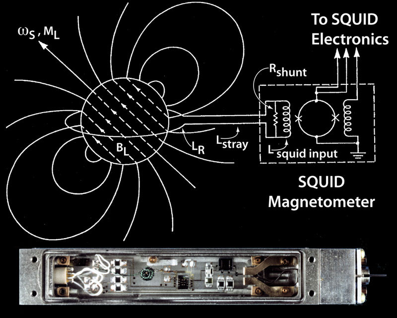
Schematic diagram and photo of a SQUID gyro readout
Solution: The answer comes through the phenomenon of superconductivity. Superconductivity provides a spin pointer which is neither optical nor mechanical as in conventional gyroscopes but magnetic. It also provides a sensitive non-interfering instrument to read the pointer, the Superconducting Quantum Interference Device (SQUID).
Superconductors have the property that when cooled below a specific temperature they completely lose their electrical resistance, hence their name. They become not just great conductors, but for steady currents, perfect ones. Additionally, when a superconductor—niobium, for example—spins it generates a magnetic field (known as the London moment after physicist Fritz London) which is exactly aligned with its spin axis. Each circling positive charge bound in the metal lattice generates a magnetic field parallel to the rotation axis. The total field produced would be very large if not for the superconducting electrons themselves responding to it. Nearly all are forced to keep up with the lattice, generating a cancelling field of their own except in a shallow surface layer about 100 atoms thick. In this layer they lag slightly behind the charged lattice leaving a small difference field- the London moment-proportional to spin rate and exactly aligned with the spin axis. Here is our pointer.
To measure the spin direction, the rotor is encircled with a thin superconducting loop connected to a SQUID (Superconducting QUantum Interference Device) magnetometer. As the orientation of the spin axis of the gyro changes, the London moment follows, changing minutely the contribution of the London moment to the magnetic field through the loop. So sensitive is the SQUID that a field change of 5 x 10-14 gauss (1/10,000,000,000,000 of the Earth's magnetic field), corresponding to a gyro tilt of 1 milliarcsecond, should be detectable within 10 hours, and a 0.1 milliarcsecond deflection should be detectable in 42 days. Feedback electronics in the SQUID readout system allow for cancellation of reaction currents in the pick-up loop, thus reducing reaction torques on the gyro to an absolutely negligible level.
The London moment readout scheme is well suited to Gravity Probe B. It is sensitive, stable, applicable to a perfect unmarked sphere and does not exert any significant reaction force on the gyroscope.
Result: The on-orbit gyroscope spin rates were lower than baselined-70 Hz or 4,200 rpm on average, rather then 130 Hz or 7,800 rpm- which increased the integration time necessary to estimate the gyroscope spin direction to the desired precision. Partially in response to the low gyro spin rates, the final vehicle roll rate was set higher than baselined (12.9 mHz or 0.77 rpm rather than 5.5 mHz or 0.33 rpm) which decreased the integration time necessary. The net result is a decrease in measurement time needed. On-orbit noise floor data shows that the SQUID readout system is capable of measuring the gyro spin axis to a precision of 1 milliarcsecond in 6 hours, and to a precision of 0.1 milliarcseconds in 4 weeks.
Dual-Sided Solar Arrays
Challenge: How do you provide continuous solar power to a spacecraft that has the unique requirements of always pointing at a single distant star, rather than the sun, while rolling continuously in orbit for 16 months or longer?

Checking the GP-B solar arrays on the spacecraft at Lockheed Martin & solar arrays deployed on a scale model of the spacecraft
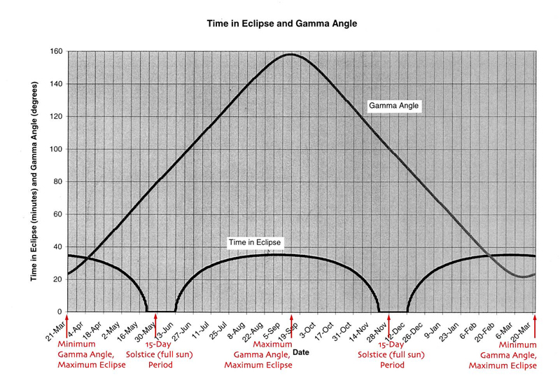
GP-B's annual orientation patterns with respect to the sun
Solution: Most satellites are designed to face the sun year around, or they have moveable solar panels that can be re-oriented to face the sun, thus maintaining positive power throughout each orbit. This is not the case with GP-B. Due to the nature of the GP-B science mission, GP-B always points at the guide star, IM Pegasi; it never points directly at the Sun, because sunlight could overwhelm the telescope's ultra-sensitive photon detectors. Furthermore, the GP-B spacecraft itself must be as free as possible from any motion disturbances that could affect the gyros and SQUID readouts. Thus, once opened, the solar arrays on the GP-B spacecraft had to be locked into fixed positions. For these reasons, GP-B's solar arrays are unique, both in their design and in their positioning on the spacecraft.
GP-B is equipped with four fixed, double-sided solar array panels, canted at such angles as to always be able to receive some solar power regardless of the season. Additionally, these double-sided panels were designed to minimize the thermal effects of the spacecraft entering and exiting eclipses, when the Earth blocks the Sun's light for up to 36 minutes per orbit. Each GP-B array contains 9,552 individual single-junction Gallium Arsenide (GaAs) solar cells that convert sunlight into electrical power with 18.5% efficiency, the standard for this type of eclipsing satellite. As sunlight is absorbed by the solar cells, its photons, or bundles of energy, are transferred to the electrons of the superconductive photo voltaic (PV) cells. The electrons in the PV cells become excited enough to escape their atoms and begin flowing, producing the current that powers the GP-B electronics.
Because the GP-B spacecraft always points at the guide star, rather than at the Sun, the angle between the spacecraft's main axis (also the telescope axis) and the Sun-called the gamma angle-varies throughout the year. Thus, the solar arrays do not receive consistent direct sunlight, and this is the reason for the unusual angles at which the solar arrays are canted.
Engineers at Lockheed Martin, who designed and built the GP-B solar arrays, had to ensure that the arrays would produce sufficient electricity in the worst-case gamma angle of approximately 22 degrees, which occurred once during the mission, on 12 September 2004. The Lockheed Martin engineers also had to design and mount the solar arrays in such a way that there would be sufficient power during the maximum 36-minute eclipse times, which occur when the gamma angle is at its maximum and minimum values (158 degrees and 22 degrees, respectively). At these angles, GP-B's orbit plane directly faces the sun-in other words, the Sun appears directly below the guide star, instead of off to one side or the other. This alignment only happened twice during the actual mission-on 12 September 2004 and 20 March 2005-and the greatest power usage and deepest depth of discharge (DOD) by the batteries occurred at these times.
Taking these worst-case alignments into account, the Lockheed Martin designers arranged the orientations of the solar panels on the spacecraft to optimize the amount of incident sunlight. Looking down on the spacecraft from the top of the telescope (that is, looking down the spacecraft's z-axis), the arrays are arranged 90 degrees apart, forming an "X" pattern. Panels 1 and 3 are canted 90 degrees into the Z-plane of the spacecraft, so that you can only see their edges looking down on the spacecraft. Panel 2 is canted 25 degrees forward in the Z- plane, towards the top of the spacecraft, and Panel 4 is canted in the opposite direction, 25 degrees backwards in the Z-plane, towards the bottom of the spacecraft. Because of this asymmetry, the spacecraft is free to rotate about the Z-axis of the telescope with minimal perturbations due to the dragging or torquing of the solar panels.
GP-B maintains a Low Earth Orbit (LEO) at an altitude of only 640 km (400 miles) about the Earth's poles. At this altitude, it has an orbital period of 97.5 minutes, eclipsing behind the Earth 14-16 times a day—almost 5,000 times a year. While in these eclipses, GP-B relies on its Super NiCAD batteries to provide power for all of the spacecraft's subsystems for the duration of each eclipse, lasting up to about 36 minutes during the peak eclipse seasons. This constant cycle of charging and discharging puts a large amount of strain on the batteries. Because of this high discharge and recharge rate, NiCAD batteries, which have been the standard in space since the 1960s, were chosen due to their extensive space heritage and robustness in high eclipse-cycle missions. GP-B's batteries have an expected lifetime of five years, and data analysis of battery performance throughout the mission has been consistent with this prediction.
Result: The solar arrays and batteries are capable of providing almost three times more power than the entire spacecraft requires, demonstrating the robustness of the system. The EPS has performed flawlessly since launch and has exceeded all expectations-not only by supporting all mission operations, but also doing so with more than ample margin.
Bonus Fact: In 1921, Einstein was awarded the Nobel Prize for his 1905 paper explaining the photoelectric effect, which is the principle on which the GP-B solar arrays function. Last year, 2005, was the 100th anniversary of Einstein's "Miracle Year"-the year in which he wrote not only his photoelectric paper, but also the special theory of relativity, and two other seminal papers.
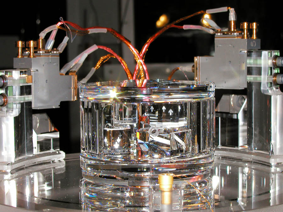
Heat-Absorbing, Hermetically Sealed Outer Probe Window
Challenge: Design a window at the outer end of the Probe that would meet all of the constraints listed below.

Window #4-the outer vacuum seal of the Probe
Constraint 1: This window forms the vacuum seal at the end of the Probe, and thus it had to be made of a material that was strong enough to withstand the pressure differential between the ultra high vacuum inside the Probe and normal atmospheric temperature and pressure outside the Probe without lensing or bulging.
Constraint 2: This window had to be a very good thermal conductor that would conduct heat uniformly in all directions from its center outward, with very little temperature rise in the center.
Constraint 3: The window had to be optically transparent, allowing the light from the guide star to enter the Probe and telescope undistorted, while at the same time, blocking electromagnetic radiation.
Constraint 4: This window had to satisfy all of the above constraints both in orbit and in extensive testing here on Earth, where the temperature and pressure differential inside and outside the Probe is much greater than in space.
Solution: That kind of window material meets all of these requirements? The answer is sapphire.
Sapphire is extremely strong, it has very high thermal conductivity, it is an electrical insulator, and it is optically transparent. Sapphire has a crystalline structure, that could cause a phenomenon called birefringence or double refractions of a single light beam. However, due to the sapphire's strength, Window #4 could be made relatively thin, and birefringence was not a problem. In addition to an anti-reflective coating, which was also applied to the three fused quartz windows, Window #4 was treated with an electromagnetic interference (EMI) coating to attenuate the ambient low-frequency and microwave electromagnetic radiation leaking into the Probe through the wide open optical aperture, both in space and on the ground. Because EMI coatings use metal, which is opaque, they reduce the optical transmission of the window. Thus, there was a trade-off between the effectiveness of the EMI shield and optical transmission requirement. Finally, Window #4 also included a thermal emissivity or "low e" coating that reduced the amount of heat it transmits into the Probe.
Perhaps the greatest challenge with Window #4 was its hermetic vacuum seal, which took many design iterations to arrive at a working solution. At the time Window #4 was constructed, rubber O-rings were typically used to create vacuum seals, but they would not have been able to withstand temperatures down to 200 K, which was a requirement for GP-B. Another option was to braze (very high temperature soldering) a metallic seal onto the outer edge of the sapphire window. However, brazing was deemed too risky, given thermal expansion issues and the very high cost of sapphire. Ultimately, the Stanford-Lockheed Martin engineering collaboration came up with a unique seal that had never before been tried: Window #4 was surrounded by an Indium-coated "C" seal, lined with a thin layer of gold against the sapphire, and held in place by a ring of springy nickel-chromium-iron alloy called Incline that is more typically used in formula race car exhaust systems.
Result: Window #4, along with its unique hermetic vacuum seal, was an engineering tour de force-a synergy of design constraints, ingenuity, and engineering prowess. This window and its hermetic vacuum seal have functioned flawlessly throughout months of pre-launch testing, and two years in orbit.
Precision Pointing Technology
Challenge: Develop a spacecraft attitude and position control system that could meet the precision pointing and drag-free flight requirements of the GP-B experiment, including all of the following constraints:
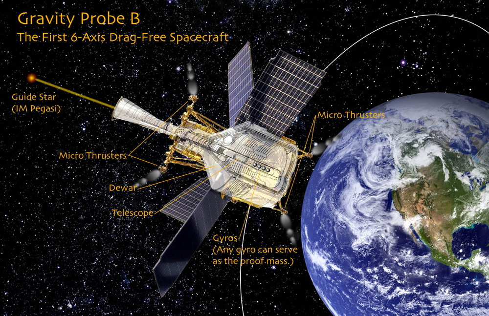
GP-B: The first spacecraft with 6 degrees of freedom in position and attitude control
Constraint 1: Provide precision attitude control for a minimum of 16 months on-orbit
Constraint 2: Maintain a continuous spacecraft roll at a selected rate, in a range of 0.1- 1.0 rpm.
Constraint 3: Keep the spacecraft pointed at a selected guide star (IM Pegasi) to within 50 milliarcseconds.
Constraint 4: Fly the entire spacecraft drag-free around one of the science gyroscopes, which have a clearance of only 32 micrometers (~0.001 inches) between the gyro rotor and its housing.
Solution: Many of the unique technologies described earlier in this section were combined to meet this challenge. The actual precision attitude control was provided by the 8 pairs of proportional micro-thrusters, described in Proportional Micro Thrusters. These thrusters were arranged so that they could control the spacecraft in all three translational degrees of freedom, as well as three additional degrees of freedom attitude control. The helium gas that constantly boiled off from the liquid helium in the dewar yielded a clever solution to providing the propellant for powering these micro-thrusters, and the porous plug provided a means of controlling this helium gas as it escaped from the dewar. The design of the dewar, itself, was also part of the solution. It had to be large enough to hold the 650 gallons of liquid helium that would maintain the cryogenic environment for the gyros to spin for at least 16 months; yet the dewar had to be physically small enough to fit in the fairing of a Boeing Delta II rocket.
The science telescope, with its Image Divider Assembly, was also an important part of the solution, since it provided the precise pointing reference for the spacecraft throughout the mission. Likewise, the Gyro Suspension System (GSS) provided feedback on the rotor position of the "proof mass" gyro, around which the spacecraft was flown drag-free.
Finally, a number of more traditional spacecraft orientation and control devices, including the star trackers, navigational rate gyros, magnetometers, magnetic torque rods, and GPS receiver were all components of spacecraft's attitude control system. Notably absent from the ATC system were reaction wheels and momentum wheels. The concern to the experiment was that these wheels could have a mass imbalance, which could interfere with the zero-g gyroscope performance.
Result: The attitude and translation control system (ATC) designed by Lockheed Martin for the GP-B spacecraft was truly an engineering "tour-de-force." It took a considerable amount of time during IOC, and part of the science phase of the mission for the GP-B and Lockheed Martin Mission Operations Team to master all the subtleties of this complex system. But once it was properly tuned up, the GP-B ATC system was able to meet the mission requirements, and it enabled the GP-B program to collect over a terabyte of data during the science phase of the mission.