WEEKLY HIGHLIGHTS FOR 23 JULY 2004:
GRAVITY PROBE B MISSION UPDATE
One day #94 of the mission, Gravity Probe B is poised to enter the home stretch of the Initialization and Orbit Checkout (IOC) phase of the mission. The spacecraft is in excellent health, and all subsystems are continuing to perform well. All four gyros are digitally suspended, with gyros #2 and #4 spinning at science mission speed—greater than 80Hz (4,800 rpm). Gyros #1 and #3 are spinning at less than 1.5 Hz (90 rpm) and are ready for full-speed spin-up next week. Fine-tuning of the Attitude and Translation Control system (ATC) is still in progress, and the ATC is performing well. The spacecraft’s roll rate is 0.52 rpm, and the science telescope is locked onto the guide star, IM Pegasi.
- Last Friday, the full-speed spin-up of gyro#2 went smoothly, with a final
spin rate of 87 Hz (5,220 rpm). Helium gas leakage from the spin-up of gyro
#2 caused gyro #4 to slow down from 105.8 Hz (6,348 rpm) to 91 Hz (5,460 rpm).
We had hoped that gyro #2 would achieve a spin rate above 100 Hz (6,000 rpm),
with less leakage effect on gyro #4. Thus, rather than spinning up gyros #1
and #3 as originally planned, we spent the past week doing analysis and running
tests—both on the spacecraft and here at Stanford—in order to
ensure that the upcoming spin-up of gyros #1 and #3 will result in higher
speeds, with less leakage effect on the remaining gyros.
- The spin rate of the gyros during the Science Phase of the mission affects the signal-to-noise ratio in the SQUID readouts of the experimental data. The noise level is quite small, but constant. The higher the gyro spin rate, the larger the London moment (magnetic field created by a spinning superconductor), and thus, the greater the signal-to-noise ratio. In ground testing prior to launch, we determined that a spin rate of 80 Hz (4,800 rpm) or greater for each gyro would provide a good signal-to-noise ratio for the science mission. However, the threshold of 80 Hz (4,800) rpm is not a hard and fast limit, so if the final spin rate of one or more gyros falls slightly below this value, this will not appreciably compromise the science data.
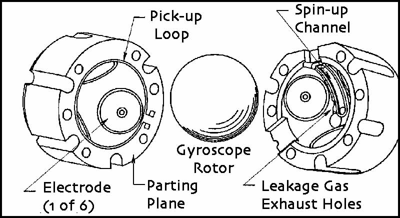
- One way to potentially increase the spin-up rate of the remaining two
gyros, while reducing the amount of helium gas leakage during spin-up is
to use the Gyro Suspension System to position the gyro rotors closer to the
spin-up channel in the gyro housing. Tests and analysis performed this past
week indicate that we can move the rotors of gyros #1 and #3 up to 30% closer
to the spin-up channels than gyros #2 and #4, and still have a safe margin
of clearance from the suspension electrodes and the gyro housings. We have
also determined that opening a second exhaust valve during spin-up may help
to reduce the pressure in the probe caused by helium leakage, thereby reducing
the spin-down effects on the remaining gyros. Both of these changes will
be implemented in the spin-up of gyros #1 and #3 next week.


- Also, this past week, we continued fine-tuning the drag-free software used by the Attitude and Translation Control system (ATC) to optimize its performance at the current and final spacecraft roll rate of 0.52 rpm. Tests from parameter changes we made to the ATC system indicate that we have reduced the time it takes to re-lock onto the guide star from as much as 15 minutes to less than 2 minutes.
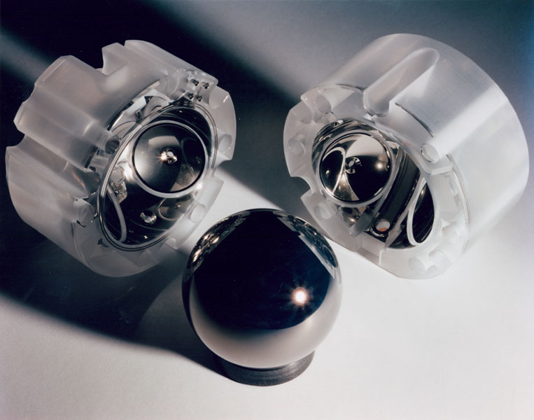
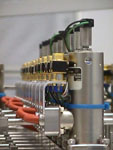
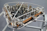
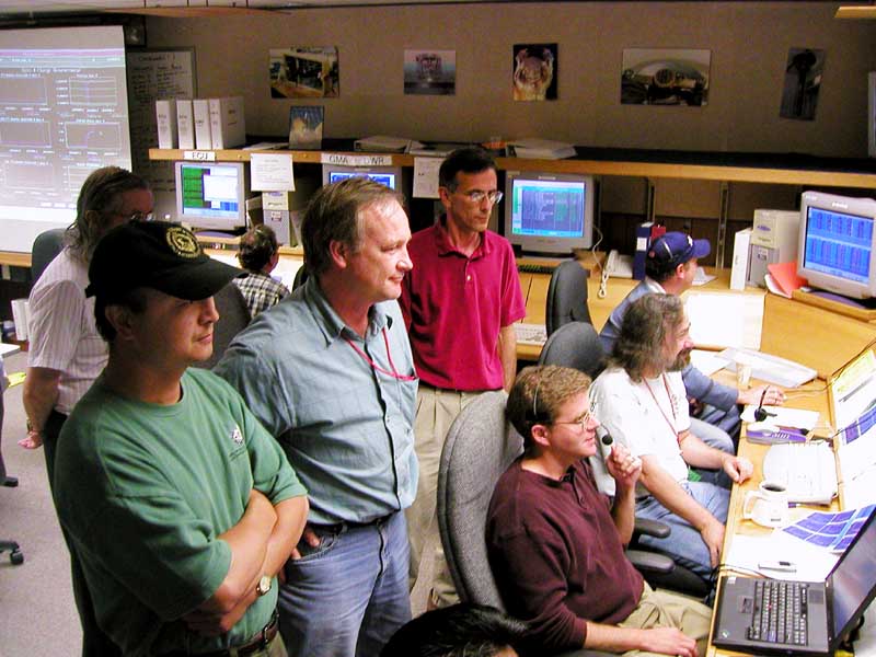
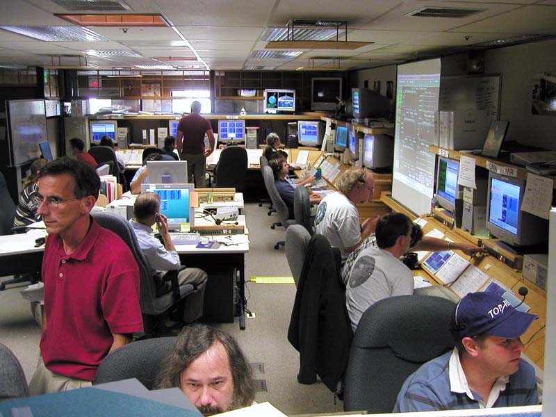
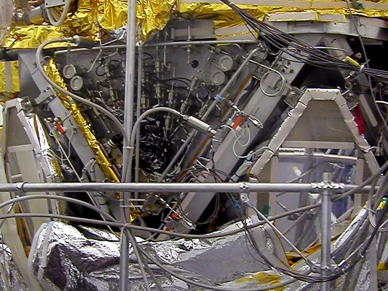
Images & Photos: The diagram of the gyro rotor and housings is also from the GP-B Image Archive. The first photo, showing the GP-B gyroscope rotor (sphere) and housings, was taken by photographer Don Harlan. In the next two photos, taken by GP-B Public Affairs Coordinator, Bob Kahn, team members in the GP-B Mission Operations Center here at Stanford are spinning up gyro #4 to full speed. The next three photos, from the Stanford GP-B Image Archive, show the [helium] Gas Management Assembly (GMA). The first of these photos is a top view of the GMA; the second shows the GMA mounted in its bay on the spacecraft frame; and the third photo shows a closeup of a row of solenoids on the GMA. The photo of the paper model of the GP-B spacecraft was taken by GP-B Public Affairs Coordinator Bob Kahn. Click on the thumbnails to view enlarged copies of these images.
More links on recent topics
- Track the satellite in the sky
- Photo, video & and news links
- Following the mission online
- Our mailing list - receive the weekly highlights via email
- The GP-B Launch Companion in Adobe Acrobat PDF format. Please note: this file is 1.6 MB, so it may take awhile to download if you have a slow Internet connection.
BUILD A PAPER MODEL OF THE GP-B SPACECRAFT
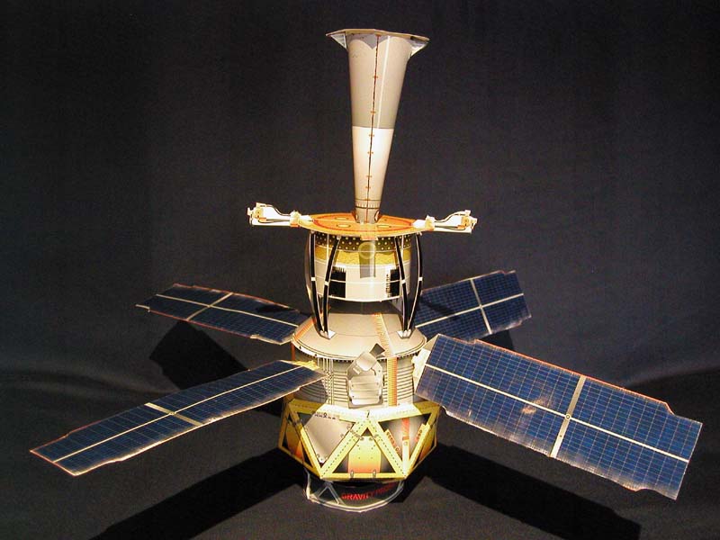 New since July 5th, we have created a 1/20 scale, paper
model of the GP-B spacecraft that you can download as a PDF file, print out, and assemble.
There are two versions of the PDF file—a 6
MB high-quality version and a 2
MB standard-quality version. Both PDF files are compatible with Adobe
Acrobat 4.0 and later. The only visible difference between the versions
is that the colors are not
as bright
and
saturated
in the standard-quality
version,
but it will download in less time for people with low-speed Internet
connections.
New since July 5th, we have created a 1/20 scale, paper
model of the GP-B spacecraft that you can download as a PDF file, print out, and assemble.
There are two versions of the PDF file—a 6
MB high-quality version and a 2
MB standard-quality version. Both PDF files are compatible with Adobe
Acrobat 4.0 and later. The only visible difference between the versions
is that the colors are not
as bright
and
saturated
in the standard-quality
version,
but it will download in less time for people with low-speed Internet
connections.
Both versions include two pages of instructions and six pages of images to cut out and assemble. You’ll need scissors, an Exacto knife, a straight edge, glue (glue sticks and hot glue guns work well), Scotch tape, two 9.5” long, 1/8” diameter wooden dowels (shish-kabob skewers work well) about 3-5 hours, and patience to assemble the model. For best results, print the cut-out pages of the model on heavyweight paper. Glossy photo paper is a bit hard to work with, but it yields a very realistic-looking model.
Previous Highlight
Index of Highlights