WEEKLY HIGHLIGHTS FOR 17 JULY 2004:
GRAVITY PROBE B MISSION UPDATE
At just under 3 months in orbit, Gravity Probe B is nearing the end of the Initialization and Orbit Checkout (IOC) phase of the mission. The spacecraft remains in excellent health, and all subsystems are continuing to perform well. All four gyros are digitally suspended, with gyros #2 and #4 spinning at science mission speed—greater than 80Hz (4,800 rpm)—and gyros #1 and #3 spinning at approximately 1.5 Hz (90 rpm), ready for full-speed spin-up. The updated drag-free thruster control software that was uploaded to the spacecraft three weeks ago to optimize performance of the Attitude and Translation Control system (ATC) is continuing to perform nominally. The spacecraft’s roll rate is 0.52 rpm, and the science telescope is being re-locked onto the guide star, IM Pegasi, following the full-speed spin-up of gyro #2 yesterday.
- This
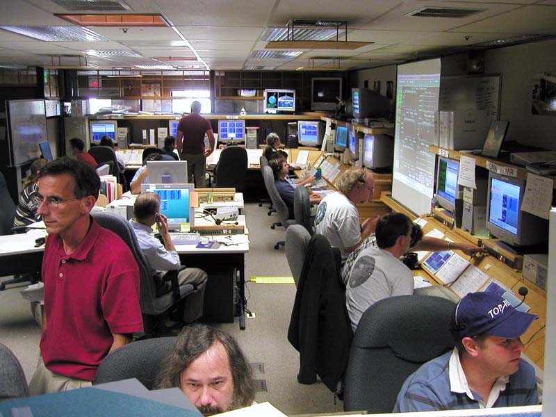
past Tuesday, July 13th, Gravity Probe B achieved a major milestone with
the successful spin-up of gyro #4 to a science-ready speed of 105.8
Hz (6,348 rpm). Second to the launch, the full-speed spin-up of the gyros
has been the next most long-awaited event in the history of GP-B. Members
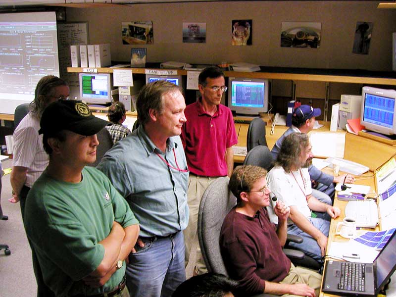
of the team were very attentive at their stations in the Mission Operations
Center (MOC) here at Stanford for 3 hours and broke into applause when the
final announcement boomed over the MOC intercom that the gyro #4 full spin-up
had been completed successfully. Yesterday, July 16th, gyro #2 underwent
the same spin-up procedure, reaching a final spin rate of 87 Hz (5,220 rpm).
Spinning up the gyros to science-ready speed is a complex and dynamic operation
that exercises the full capabilities of the Gyro Suspension System (GSS)
and requires a high level of concentration and coordination on the part of
the GP-B Team. Following is an overview of the process.
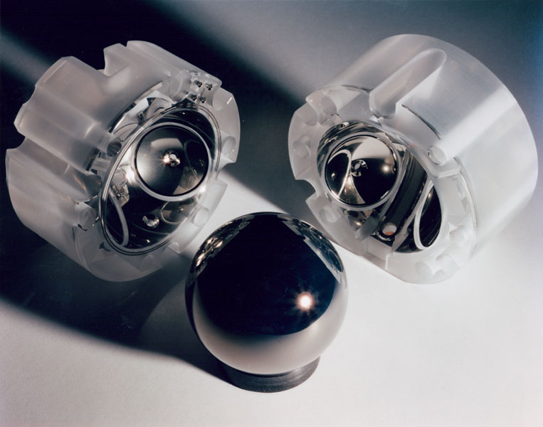
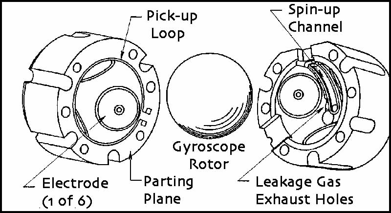
- First,
commands are sent to the GSS to move the gyro rotor (sphere) very close
to the spin-up channel (about 1/100th of the edge of a sheet of paper)
in one half of the gyro’s housing.

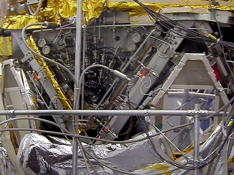
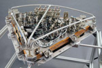 Ultra-pure (99.99999%) helium
gas is streamed from the Gas Management Assembly (GMA), mounted in a bay
on the spacecraft frame, through tubing that enters the “top hat” (the
thermal interface at the top of the probe) and travels down to the gyro
housings in the Science Instrument Assembly (SIA) at the bottom of the
probe. As the helium gas descends into the probe, which is at a temperature
of approximately 1.8 Kelvin, the gas cools down from 273 Kelvin to around
12 Kelvin.
Ultra-pure (99.99999%) helium
gas is streamed from the Gas Management Assembly (GMA), mounted in a bay
on the spacecraft frame, through tubing that enters the “top hat” (the
thermal interface at the top of the probe) and travels down to the gyro
housings in the Science Instrument Assembly (SIA) at the bottom of the
probe. As the helium gas descends into the probe, which is at a temperature
of approximately 1.8 Kelvin, the gas cools down from 273 Kelvin to around
12 Kelvin. - Before entering the spin-up channel in one of the gyro housings, the gas
is passed through a combination filter/heater. The filter, which is made
of sintered titanium, removes any impurities that may have been imparted
to the helium on its journey into the probe. The heater enables the helium
to be warmed slightly, which increases its adhesion to the ultra-smooth surface
of the gyro rotor.
The filtered and warmed helium then passes through the
spin-up channel in one half of the gyro housing, and most of the gas evacuates
into space through an exhaust system.
 However, some of the helium leaks into
the housings of the other gyros, causing their spin rates to decrease up
to 20% over a full spin-up period of 2-3 hours.
However, some of the helium leaks into
the housings of the other gyros, causing their spin rates to decrease up
to 20% over a full spin-up period of 2-3 hours.
- For this reason, the order in which the gyros are spun up is very important. Earlier in the IOC phase, the 3 Hz (180 rpm) spin-up provided information on the helium leakage rate of each gyro. Gyro #4, which had the highest leakage rate, was spun-up to full speed first, so that helium leaked from its spin-up would not affect other gyros that were already at science mission speed. The remaining gyros are then spun-up in decreasing order of their helium leakage rates—gyro #2, gyro #1, and finally, gyro #3.
- Each full-speed spin-up takes most of a day. In the morning, helium gas is flowed over the gyro for 90 seconds, and tests are run to ensure that the helium leakage rate for that gyro corresponds to previous measurements. If everything checks out, the full-speed spin-up, in which helium gas is flowed over the rotors for 2-3 hours, commences early in the afternoon. The GP-B team controls the spin-up process by sending commands from the Mission Operations Center (MOC) here at Stanford to the spacecraft in real-time. For example, they send commands to open or close the GMA valves to flow helium through the gyro’s spin-up channel. They also control the amount of heat applied to the gas before it enters the gyro spin-up channel, and they control opening and closing of exhaust valves. Real-time telemetry provides immediate feedback on the progress of the spin-up so that various parameters can be adjusted as necessary.


- The successful spin-up of gyro #4 to full speed enabled us to spin-up gyro #2. Gyro #2 topped out at 87 Hz (5,220 rpm), which is only slightly above the minimum spin rate of 80 Hz (4,800 rpm) required for the science experiment. Also, the helium gas leakage from the Gyro 2 spin-up slowed gyro #4 down to 91Hz (5,460 rpm). We are taking some time to evaluate the data from the first two spin-up procedures and to perform some ground-based tests before spinning up gyros #1 and #3 to full speed.
- Meanwhile, we are fine-tuning the drag-free software used by the Attitude and Translation Control system (ATC) to optimize its performance at the current and final spacecraft roll rate of 0.52 rpm. For part of each orbit, the spacecraft passes behind the Earth, causing the telescope to lose visual contact with the guide star. During this “eclipse” period, two standard external rate gyroscopes, plus the star trackers on either side of the spacecraft, enable the ATC to keep the spacecraft/telescope pointed towards the guide star. When the spacecraft emerges over the North Pole and the guide star becomes visible again, the telescope must be re-locked onto it. This re-locking has been taking up to 15 minutes, and the fine-tuning will speed up this process considerably.
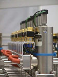
Images & Photos: The first photo, showing the GP-B gyroscope rotor (sphere) and housings, was taken by photographer Don Harlan. In the next two photos, taken by GP-B Public Affairs Coordinator, Bob Kahn, team members in the GP-B Mission Operations Center here at Stanford are spinning up gyro #4 to full speed. The next three photos, from the Stanford GP-B Image Archive, show the [helium] Gas Management Assembly (GMA). The first of these photos is a top view of the GMA; the second shows the GMA mounted in its bay on the spacecraft frame; and the third photo shows a closeup of a row of solenoids on the GMA. The diagram of the gyro rotor and housings is also from the GP-B Image Archive. The photo of the paper model of the GP-B spacecraft was taken by GP-B Public Affairs Coordinator Bob Kahn. Click on the thumbnails to view enlarged copies of these images.
More links on recent topics
- Track the satellite in the sky
- Photo, video & and news links
- Following the mission online
- Our mailing list - receive the weekly highlights via email
- The GP-B Launch Companion in Adobe Acrobat PDF format. Please note: this file is 1.6 MB, so it may take awhile to download if you have a slow Internet connection.
BUILD A PAPER MODEL OF THE GP-B SPACECRAFT
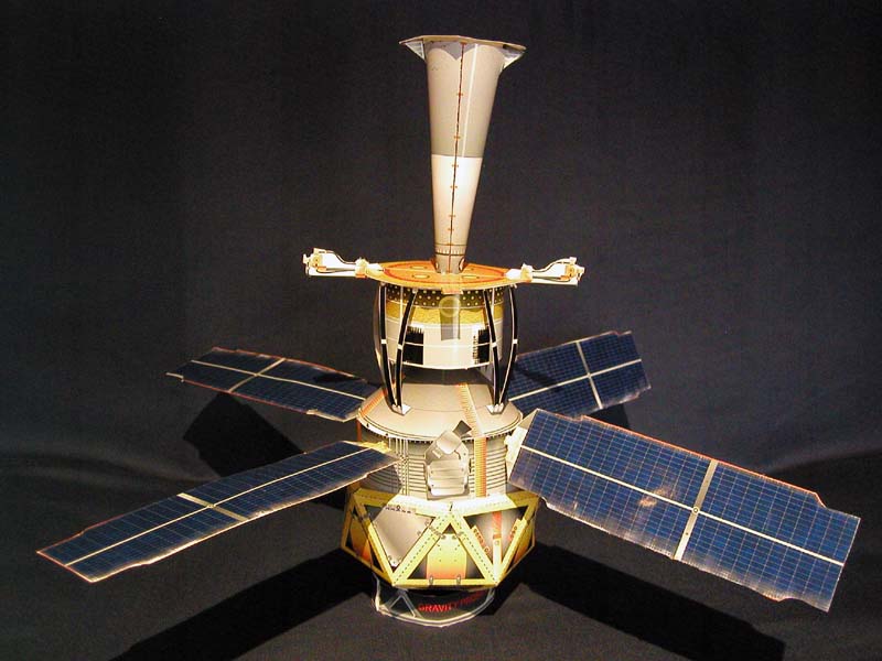 New since July 5th, we have created a 1/20 scale, paper
model of the GP-B spacecraft that you can download as a PDF file, print out, and assemble.
There are two versions of the PDF file—a 6
MB high-quality version and a 2
MB standard-quality version. Both PDF files are compatible with Adobe
Acrobat 4.0 and later. The only visible difference between the versions
is that the colors are not
as bright
and
saturated
in the standard-quality
version,
but it will download in less time for people with low-speed Internet
connections.
New since July 5th, we have created a 1/20 scale, paper
model of the GP-B spacecraft that you can download as a PDF file, print out, and assemble.
There are two versions of the PDF file—a 6
MB high-quality version and a 2
MB standard-quality version. Both PDF files are compatible with Adobe
Acrobat 4.0 and later. The only visible difference between the versions
is that the colors are not
as bright
and
saturated
in the standard-quality
version,
but it will download in less time for people with low-speed Internet
connections.
Both versions include two pages of instructions and six pages of images to cut out and assemble. You’ll need scissors, an Exacto knife, a straight edge, glue (glue sticks and hot glue guns work well), Scotch tape, two 9.5” long, 1/8” diameter wooden dowels (shish-kabob skewers work well) about 3-5 hours, and patience to assemble the model. For best results, print the cut-out pages of the model on heavyweight paper. Glossy photo paper is a bit hard to work with, but it yields a very realistic-looking model.
Previous Highlight
Index of Highlights