GP-B Mission News, November 2006 — Polhode Motion in the GP-B Gyros
Editor’s Note
I have often mentioned the term “polhode” in these status updates, with a parenthetical reference to the motion of our gyroscope rotors. Typically, a few days later I then receive a number of email messages, asking for more information about this exotic word—what is the polhode motion of the gyro rotors, and why is it important to the GP-B experiment? In this month’s GP-B Mission News story, I will attempt to answer these questions in more detail. I am most grateful to our GP-B science team for their time and invaluable assistance in writing this story. —Bob Kahn
The Origins the Word Polhode and the Motion It Describes

The concept of polhode motion dates back to the 18th century, when the preeminent Swiss/Russian mathematician and astronomer, Leonhard Euler, derived a set of equations that described the dynamics of rigid bodies in torque-free motion. In particular, Euler and his contemporaries Jean d’Alembert, Louis Lagrange, and others noticed small variations in latitude due to wobbling of the Earth around its polar spin axis. A portion of this wobble—later to be called the Earth’s polhode motion—was due to the natural, torque-free behavior of the rotating Earth. Incorrectly assuming that the Earth was a completely rigid body, they calculated the period of Earth’s polhode wobble to be about 9-10 months.

During the mid 19th century, Louis Poinsot, a French geometer, developed a geometric interpretation of the physics of rotating bodies that provided a much-welcomed visual counterpart to Euler’s algebraic equations. Poinsot was a contemporary of Leon Foucault, who invented the gyroscope and whose famous pendulum experiments provided incontrovertible evidence the Earth rotates. In the fashion of the day, Poinsot coined the terms polhode and its counterpart, herpolhode, to describe this wobble in the motion of rotating rigid bodies. Poinsot derived these terms from the ancient Greek words, POLE=pivot or end of an axis and ODE=path or way—thus, polhode is the path of the pole.

Poinsot’s geometric interpretation of Earth’s polhode motion was still based on the incorrect assumption that the Earth was a completely rigid rotating body. It was not until 1891 that the American astronomer, Seth Carlo Chandler, made measurements showing that there was a periodic motion of 14 months in the Earth’s wobble and suggesting that this was the polhode motion. Initially, Chandler’s measurement, now referred to as the “Chandler Wobble,” was dismissed because it was significantly greater than the long-accepted 9-10 month period calculated by Euler, Poinsot, et al. and because Chandler was unable convincingly to explain this discrepancy. However, within months, another American astronomer, Simon Newcomb, realized that Chandler was correct and provided a plausible reason for Chandler’s measurements. Newcomb realized that the Earth’s mass is partly rigid and partly elastic, and that the elastic component has no effect on the Earth’s polhode period, because the elastic part of the Earth’s mass stretches so that it is always symmetrical about the Earth’s spin axis. The rigid part of the Earth’s mass is not symmetrically distributed, and this is what causes the Chandler Wobble—or more precisely, the Earth’s polhode path.
What Exactly is the Polhode Motion?
A way to visualize polhode motion is as follows: Take a trip on the space shuttle, where you'll be in free-fall around the Earth. With a pen, place a marker dot on the surface of a solid object, and then set the object spinning about the dot at the rate of one revolution per second in that weightless environment. Now, point a strobe light, flashing once per second, at the rotating object. If there is no polhode motion, the object will appear motionless, and the dot will remain stationary. However, if the object does exhibit polhode motion, the dot will appear to move in an elliptical pattern over the period of the polhode. If the object has equal principal inertias in two axes, the polhode path will be circular. If you were able to touch a pen to the spin axis of the object while it was spinning, the ink would trace out this elliptical or circular polhode pattern on the surface of the object.
To give a more intuitive sense of meaning to this motion, try the following experiment with a rectangular, solid object whose length, width, and height differ—for example a small block of wood (a book rubber-banded shut or other rectangular object of differing dimensions will also work):
 |
|
If you don’t have a block of wood handy, the animations below show a simulated block of wood spinning about each of its three axes of rotation.
| Rotatonal Motion of an Object around Its Three Principal Axes of Inertia | ||
|---|---|---|
 |
 |
 |
| Principal Axis of Minimum Inertia Simulation | Principal Axis of Maximum Inertia Simulation | Principal Axis of Intermediate Inertia Simulation |
| Stable Rotation | Stable Rotation | Unstable Rotation |
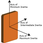
From this experiment and/or the animations above, you can see that the block spins stably about its axis of minimum inertia (the longest axis through the top and bottom in the drawing). It also spins stably about its axis of maximum inertia (the shortest axis through the center from front to back in the drawing). However, it tumbles and will never spin uniformly about its axis of intermediate inertia. This twisting or tumbling pattern, which traces out the shape of an ellipse in the frame of the body’s rotation, is called the polhode motion, and it is a property of all rotating bodies. The path traced out by the motion of the axis about which the block is spinning is the polhode path. It’s hard to see the polhode path for the axes of minimum and maximum inertia, but the tumbling motion about the axis of intermediate inertia is a dramatic example of a polhode path.
Every solid body inherently has three principal axes of symmetry through its center of mass, and each of these axes has a corresponding moment of inertia. The moment of inertia about an axis is a measurement of how difficult it is to accelerate the body about that axis. The closer the concentration of mass to the axis, the smaller the torque required to get it spinning at the same rate about that axis.
The shortest axis of symmetry (i.e. the axis through the center of the wood block from front to back) has the largest or maximum moment of inertia. If energy is dissipated while an object is rotating, this will cause the polhode motion about this maximum axis of inertia to damp out or stabilize, with the polhode path becoming a smaller and smaller ellipse or circle, closing in on the axis.
The intermediate axis of symmetry (e.g. the axis through the center of the block of wood, from side to side) corresponds to an intermediate moment of inertia that lies between the minimum and maximum moments of inertia. A body is never stable when spinning about this axis, and dissipated energy will cause the polhode to start migrating to the object’s axis of maximum inertia. The transition point between two stable axes of rotation is called the “separatrix,” along which the angular velocity passes through the axis of intermediate inertia.
The longest axis of symmetry (i.e. the axis through the center the wood block, from top to bottom) corresponds to the smallest or minimum moment of inertia. Rotation about this axis is also stable, but given enough time, such as a body rotating in zero g, any perturbations due to energy dissipation or torques would cause the polhode path to expand, in larger and larger ellipses or circles, and eventually migrate through the separatrix and its axis of intermediate inertia to its axis of maximum inertia.
It is important to note that these changes in the orientation of the body as it spins may not be due to external torques, but rather result from energy dissipated internally as the body is spinning. Even if angular momentum is conserved (no external torques), internal energy can be dissipated during rotation if the body is not perfectly rigid, and any rotating body will continue to change its orientation until it has stabilized around its axis of maximum inertia, where the amount of energy corresponding to its angular momentum is least. You can see this changing orientation in the two NASA video clips below. The first clip shows a small rectangular electronic component freely rotating and tumbling about its intermediate axis. The second is a 5-minute video clip, in which Astronaut, Owen Garriott, experiments with a spinning drink dispenser aboard the NASA Skylab orbiting laboratory.
| Video Clips Of Objects Rotating in Zero G | |
|---|---|
|
10-Second video of object in NASA Skylab
tumbling about Its
principal axis of intermediate inertia
Click the Play button to start the video |
6-Minute video of Astronaut Owen Garriott demonstrating the changing polhode paths of a partially-full drink bottle rotating in zero G aboard the NASA Skylab
Click the Play button to start the video |
- Note: The video clips above may require that the Apple QuickTime plug-in be installed in your Web browser. Click here to download the free QuickTime 7 Media Player and browser plugin for Mac OS or Windows 2000/XP.
Polhode Behavior in GP-B's Spherical Gyroscopes
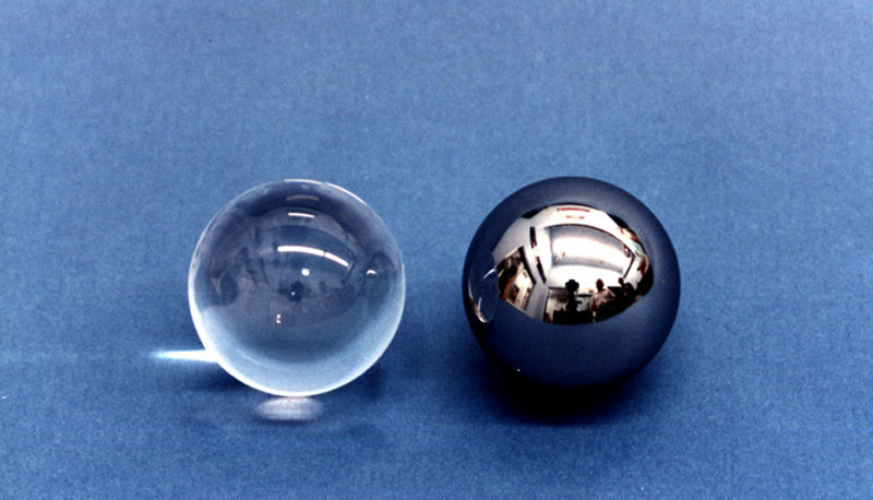
Having followed the discussion of polhode motion thus far, you may be wondering why the GP-B gyroscope rotors—listed in the Guinness Database of World Records as the most spherical objects ever made—would exhibit any polhode behavior at all? Indeed, in a perfectly spherical and homogeneous object, in which all three principal axes of inertia are identical, the polhode period around any of these axes would become infinitely long, and for all practical purposes would not exist.
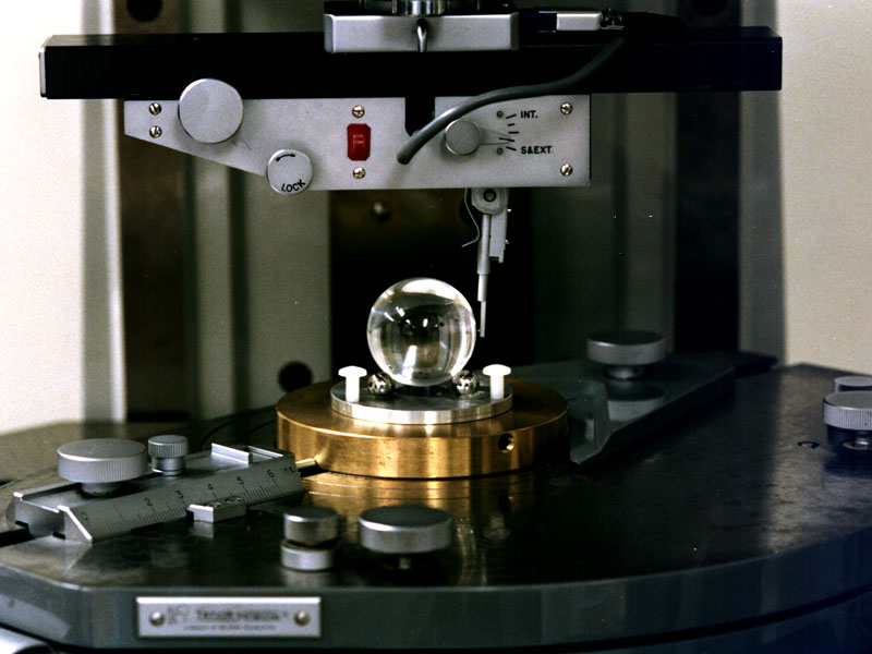
However, as round as they are, the GP-B rotors are not “perfect” spheres. The sphericity and uniformity of the fused quartz substrate allow the moments of inertia among the principal axes in each gyro rotor to be matched to about 1 part in a million; this together with its spin rate determine the polholde period of the rotor. But it is the relative magnitudes of the differences in moments of inertial between the axes that determine the shape of a rotor's polhode path.
All of this was anticipated. Prior to launch, the expected behavior of the GP-B gyro rotors was modeled extensively. The prevailing consensus was that because the rotors were close enough to being perfectly homogeneous spheres, they would all exhibit polhode motion, with long periods, and that the polhode paths for each rotor would not change significantly over the life of the experiment.
As expected, the four gyros did, indeed, exhibit long polhode periods. When you toss a block of wood about different axes of symmetry into the air, you can begin to see the polhode path within 3-4 rotations. With the GP-B gyro rotors, it took between 52 minutes and 15 hours (average=5 hours) to see the polhode patterns emerge in various analyses—that works out to a quarter of a million to over three million gyro rotor rotations per polhode period!
However, contrary to initial expectations, the polhode paths of the four gyros changed significantly over the life of the experiment. With such small differences between the three principal axes of inertia in the GP-B gyro rotors, there was no way to know about which axis each gyro was initially spun up; the location of the three principal axes of inertia for each gyro had to be determined empirically after the gyros were spinning.
Using the data generated by the Gyro Suspension System (GSS) and trapped magnetic flux in the SQUID readouts, members of our GP-B team have created time histories of the polhode periods of the four gyro rotors. These histories revealed that gyros #1 and #2 started out spinning close to their axis of minimum inertia. As a result, over the course of the mission, their polhode paths migrated through the separatrix to their axes of maximum inertia, where they slowly damped out as a very small fraction of the rotational energy was dissipated. Gyros #3 and #4, on the other hand, began spinning close to their axis of maximum inertia, so for both of these gyros, the polhode paths simply became smaller and smaller as their internal energy dissipated and their polhode paths damped out. For highly symmetric objects, like the GP-B gyro rotors, this damping out of the polhode motion - polhode paths becoming smaller and smaller ellipses or circles, closing in on the axis - can require quite a long time. For example, it took almost the entire mission for the polhode motion of gyro #1 to close in on its axis of maximum inertia, and the polhode motion of gyro #2 was still in the process of damping out when we stopped collecting data at the end of the flight mission.
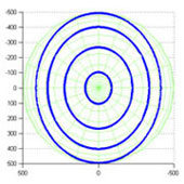
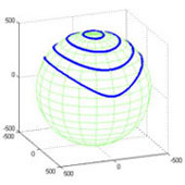
The three animations below were created from actual data for gyro #1. They display a complete polhode path at three time periods in the flight mission. The path in each animation is shown as a sequence of snapshots, taken at the gyro spin frequency. In other words, imagine that a strobe light is flashed and a snapshot of the rotor's orientation taken once per revolution as the rotor traces out one complete polhode path. (Note: these animations are set to loop continuously, so the motion on each path is being repated over and over again.)
The color on the gyro rotor is essentially a topographical surface map of the rotor's surface, as measured by the Gyro Suspension Sytem and SQUID readout on orbit. The red areas represent the highest points on the surface; the blue areas are the lowest, with the yellow-green areas in between. If the rotor were actually painted in this rainbow-colored pattern, it would show this motion under a strobe light flashing once per revolution.
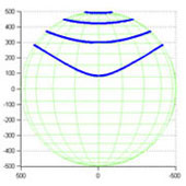
The small, fixed hole on the top of each rotor represents the axis around which the rotor is spinning—that is, the gyro's spin axis. Notice that the spin axis is fixed in its vertical position, while the rotor's orientation changes continually. If the strobe light were turned off, you would see a blur of color as the rotor rotates around its fixed spin axis. Furthermore, If a pen were placed in the small spin-axis "hole," just touching the rotor surface, it would trace out the polhode path on the rotor. The series of plots below the animations shows the changing polhode path of gyro #1 from early in the mission (large path) to late in the mission (very small path).
| Early Mission | Mid Mission | Late Mission |
|---|---|---|
 |
 |
 |
| Large Polhode Path | Moderate Polhode Path | Very Small Polhode Path |
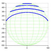
| Changing Polhode Paths on Gyro #1: Large Path=early mission; Small Path=late mision | |||
|---|---|---|---|
 |
 |
 |
 |
| Top View | Front View | Side View | Perspective View |
Mechanism Behind the Gyro Polhode Behavior
One of the important challenges embraced by GP-B team during the data analysis period has been to explain the unexpected changing polhode paths in the GP-B gyros. Data collected during the mission clearly shows that the polhode periods of all four gyros did not remain constant, but rather they damped out in all four gyros, and in two of the gyros, the polhode paths migrated between inertial axes. More importantly, the wide variation in spin-down rates suggests that some mechanism inherent to each individual gyro might best account for the changing polhode paths. But what kind of mechanism could this be?
Given the almost perfectly spherical and homogeneous nature of the GP-B gyro rotors, there are two possibilities:
- Internal energy dissipation
- External torques with just the right frequency
It turns out that a combination of these is at work. Because of the extreme symmetry of the rotor, the polhode path is very sensitive to internal energy dissipation—on the order of 10^-16 watts! Like the Earth described above, the gyroscope is somewhat elastic, and bulges at its equator by about 10 nm. Since the spin axis moves over the surface of the body driven by the polhode motion, this bulge moves with respect to the principal axes. Due to small defects in the body of the rotor or subtle interface issues between the rotor and its niobium coating, rotational energy can be dissipated internally. This causes the polhode path to change without changing the overall angular momentum of the rotor. (An extreme example of internal dissipation of this type is easily seen when using the old trick to check whether or not an egg is fully cooked: When spinning a raw egg on the table, you will find that its spin rate decreases rapidly, while a hard boiled egg spins happily at the same rate for some time). When this internal dissipation is combined with the spin down torque due to gas damping and other effects, a high fidelity model of the polhode period history is found.
Effects of Gyro Polhode Motion on the Experimental Results
The fact that the polhode paths of the four gyros varied slowly over the course of the mission did not pose an insurmountable problem. Rather, it has increased the complexity of the data analysis and lengthened the time required to complete it. It was necessary to model the time-varying polhode paths accurately for each gyro and to ensure that the modeled paths correlate precisely with the actual data. Our science team has done this and is continuing to improve their models. We are now able to account for the polhode motion of our four gyros accurately over the life of the experiment.
References
If you are interested in learning more about polhode behavior, the following references may be helpful:
- Donald T. Greenwood. Principles of Dynamics, 2nd Ed. (Prentice-Hall, 1988)
- Herbert Goldstein. Classical Mechanics, 3rd Ed. (Addison Wesley, 2002)