WEEKLY HIGHLIGHTS FOR 5 NOVEMBER 2004:
GRAVITY PROBE B MISSION UPDATE
As of mission Day #199, all vehicle and payload systems remain in good health. We have now completed nine weeks of data collection, and the quality of the data continues to be excellent. The spacecraft is maintaining a constant roll rate of 0.7742 rpm (77.5 seconds per revolution) and flying drag-free around gyro #3. The flow of helium from the Dewar through the micro thrusters is nominal, and the Dewar temperature is stable at 1.82 kelvin.
Once again, this past week has been a relatively quiet one for the GP-B spacecraft. Adjustments that we made to the drag-free suspension parameters have prevented any further harmonic coupling between the drag-free control system and helium sloshing in the Dewar. As a result, the previously reported oscillations in the drag-free control force have completely disappeared. We will continue to monitor the drag-free control system and any motion of helium in the Dewar, but this is no longer considered to be an issue.
Likewise, increasing the signal to noise ratio in the Gyro Suspension System (GSS) position readouts of gyros #3 and #1 has mitigated the problems we experienced with these gyros unexpectedly transitioning to analog suspension mode. Both gyros #1 and #3 have remained digitally suspended since we made these adjustments, so we also consider this issue to be closed.
The Science Telescope On-board the GP-B Spacecraft
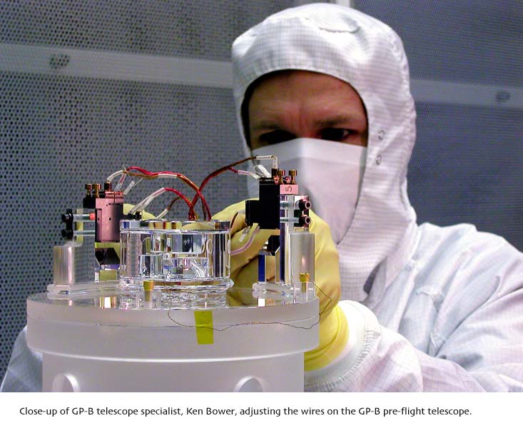
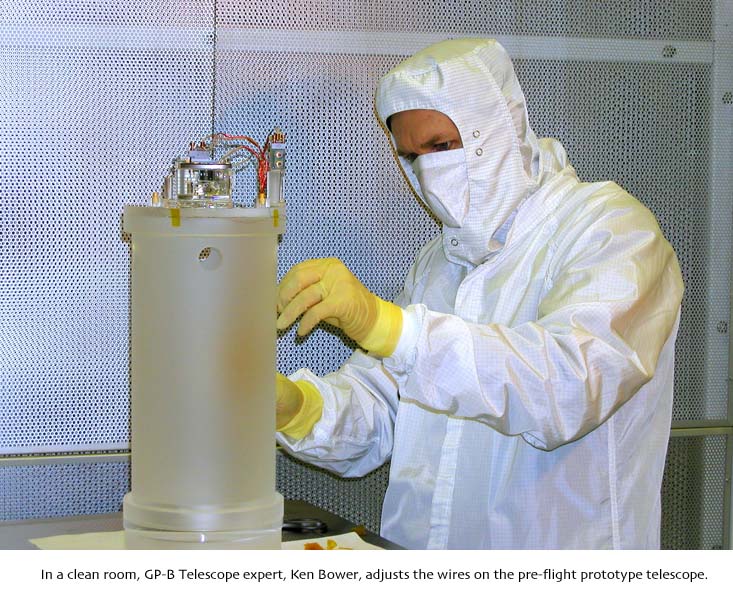
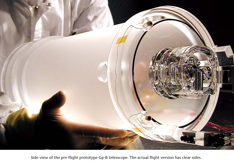
This past week, we moved our pre-flight prototype science telescope into a clean room to photograph it, before returning it to its sealed display case in our GP-B lobby here at Stanford. The science telescope is both a beautifully crafted instrument and a marvel of engineering, as you can see in the photos we’ve posted with this week’s highlights. For those readers who are interested, following is some information about the GP-B science telescope.
The pre-flight prototype telescope in the photos is nearly identical to one currently on-board the spacecraft.
Noticeable differences include slightly different Detector Package Assemblies (DPA) and more auxiliary sensors on the top rim of the flight telescope.
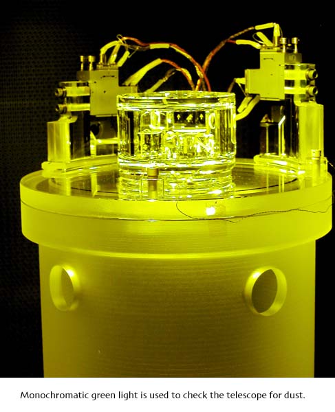 Also, the Image Divider Assembly (IDA) on the front end of the flight telescope is covered by a "reticle plate" that works as an aperture stop for the telescope and also provided an alignment reference for integrating the telescope with the quartz block that houses the gyros. (The reticle plate also obscures the view of the sparkling interior of the IDA.) However, the most noticeable difference between the flight telescope and the pre-flight prototype is that the flight telescope has a polished metering tube (barrel) whereas the metering tube of the prototype is fine-ground, giving it a frosted appearance. The reason for this change is that while the fine-ground version was less expensive to make, it was much easier to see dust on the clear version. Because this telescope focuses light on a spot that is only 1 mil (1/1000 of an inch) in size, a single speck of dust could obscure the focused beam, so the telescope must be kept extremely clean. For this reason, it was assembled in a clean room, and a monochromatic green light was used to detect any dust particles, which were then carefully removed.
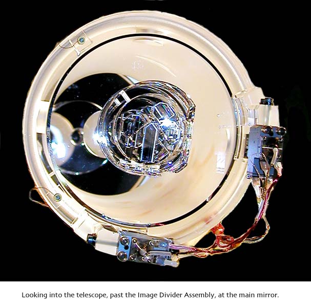
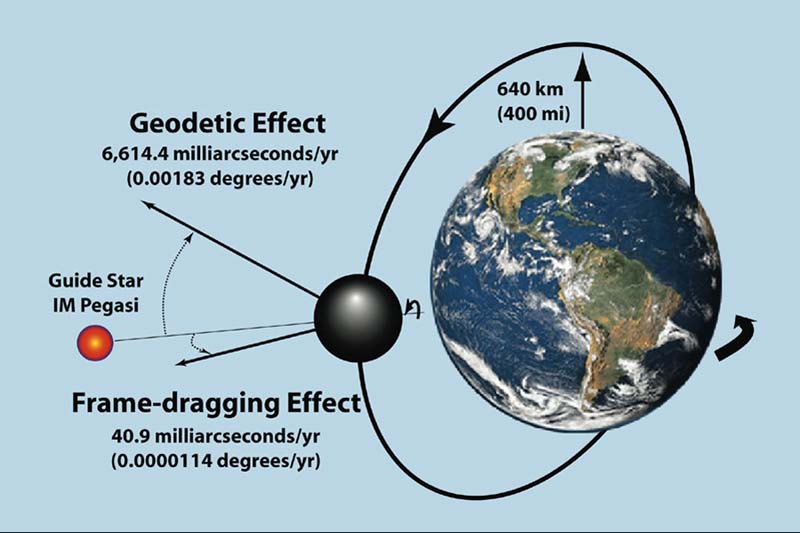
Our science telescope is a variation of a Cassegrain reflecting type, in which a series of three mirrors folds the incoming beam of light from the guide star (IM Pegasi or HR 8703) into a single spot, which is then divided into four quadrants by the the IDA, centered on top of the clear front end cap of the telescope. This design enables us to achieve a focal length of 3.8 meters (12.5 feet) in a telescope that is only 35.6 centimeters (14 inches) long, with a primary mirror 14.2 centimeters (5.6 inches) in diameter at the bottom of the telescope.
 Because the line of sight from the telescope to the guide star provides the reference against which gyroscope spin axis drift is measured, image stability was a critical requirement in its construction. To accomplish this, the telescope had to be able to remain focused during testing from room temperature to cryogenic temperatures—a range of 300 degrees Celsius (572 degrees Fahrenheit). Astronomical telescopes tend to lose focus with only slight changes in ambient temperature (and early GP-B telescope prototypes were no exception), so this temperature insensitivity requirement was a formidable challenge.
The solution was to fabricate all of the optical parts of the telescope—the barrel, the mirrors, the front-end cap, and the IDA—from a single boule (a cylindrical lump of material for synthetic gems) of extremely high quality fused quartz ( also known as amorphous quartz). Specifically, a fused quartz boule is made from hand-selected pieces of natural quartz that are flame-fused together. The fused quartz was purchased from the German company, Heraeus. It was graded “Herasil 1 Top,” the highest grade obtainable in the size boule required for the telescope. The very highest grade of fused quartz, called Homosil, is also made by Heraeus, but it is only available in small boules. Thus, Homosil was used to fabricate the GP-B gyro rotors (spheres).  In addition to its uniform density, fused quartz was chosen because it remains stable at cryogenic temperatures, and it has no magnetic properties, and it is has excellent optical properties.
Adjacent parts of the telescope were cut from adjacent sections of this quartz boule, ensuring structural homogeneity and a common coefficient of expansion/contraction throughout the telescope. This same boule of fused quartz was also used to form the quartz block, which is bonded to the base of the telescope. The bond between the telescope and quartz block needed to work in the vacuum of space, not create any magnetic disturbances, and be capable of going from room temperature to cryogenic temperatures without cracking. No glue in existence has all of these properties, so GP-B scientist, Jason Gwo, developed a new optical bonding technique, patented under the name OptoBond™, specifically for this purpose.
The sighting axis of the telescope defines the roll axis of the spacecraft, and this is also the alignment for the centers of all four gyros and the SQUID pickup loops mounted on each gyro housing. To achieve this exacting alignment, the telescope parts had to be machined with extreme precision and assembled with painstaking care. Each of the surfaces of the telescope and all of its components contain alignment reference marks. As the telescope and quartz block were assembled, these reference marks were used to minimize alignment errors in each individual part of the assembly to one arc-second (1/3600th of a degree) or less. After all the parts were assembled, further alignment corrections were made to minimize the aggregate of all alignment errors to less than 1/4 arc-minute (1/240th of a degree). For example, the three mirrors in the telescope had to be aligned to focus the incoming starlight along the telescope’s sighting axis down to a point 1 mil (1/1000th of an inch) in diameter, and then the IDA assembly had to be perfectly aligned in the center of the telescope’s front end, to receive the focused beam. It was also the alignment reference for the centers of all four gyros. This was a formidable job!
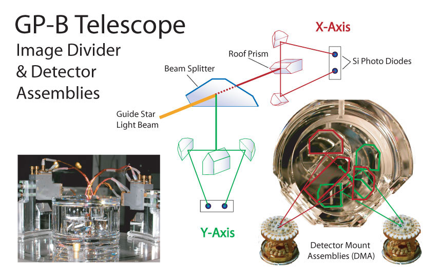
Unlike normal astronomical telescopes which focus an image of a celestial body on an eyepiece for viewing, the purpose of the GP-B science telescope is to keep the entire GP-B spacecraft pointed at the exact center of the guide star. To accomplish this ultra-precise pointing task, the GP-B telescope has a slightly different optical path from a traditional Cassegrain telescope, and it includes a special optical package (the IDA) that divides the incoming light beam into four quadrants (two in the X plane and two in the Y plane) and then sends the two half half beams for each plane to special electronics packages that compare them.

In a traditional Cassegrain telescope, light enters at the front end of the instrument, bounces off the primary mirror at the back end onto a secondary mirror at the front, and then bounces back through a hole in the primary mirror to an eyepiece assembly at the bottom of the instrument. In the GP-B telescope, light follows the same path for the first three segments, but a third mirror reflects the light bounced from the secondary mirror back to the front of the telescope, where it is focused on the IDA.
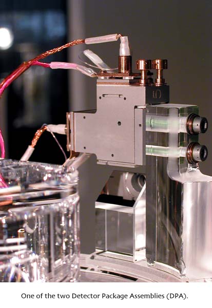

The IDA box, which has a sparkling jewel-like appearance, contains a half-silvered mirror, mounted at a 45-degree angle. This beam-splitter mirror sends half of the incoming beam straight through it to the Y-axis roof prism (a V-shaped mirror) , where the 1 mil beam spot is split into two "D-halves." These D-halves are then sent to a Detector Package Assembly (DPA), mounted on the rim of the telescope’s front end. The beam-splitter mirror reflects the other half of the beam at a 90-degree angle to the X-axis roof prism, where that spot is split into two D-halves and steered into the other DPA, mounted 1/4 of the way around the rim of the telescope. Each DPA contains another beam splitter and two Detector Mount Assemblies (DMAs) that are smaller than a dime in diameter. (In each DPA, only one of the DMAs is used; the second one is a backup.)
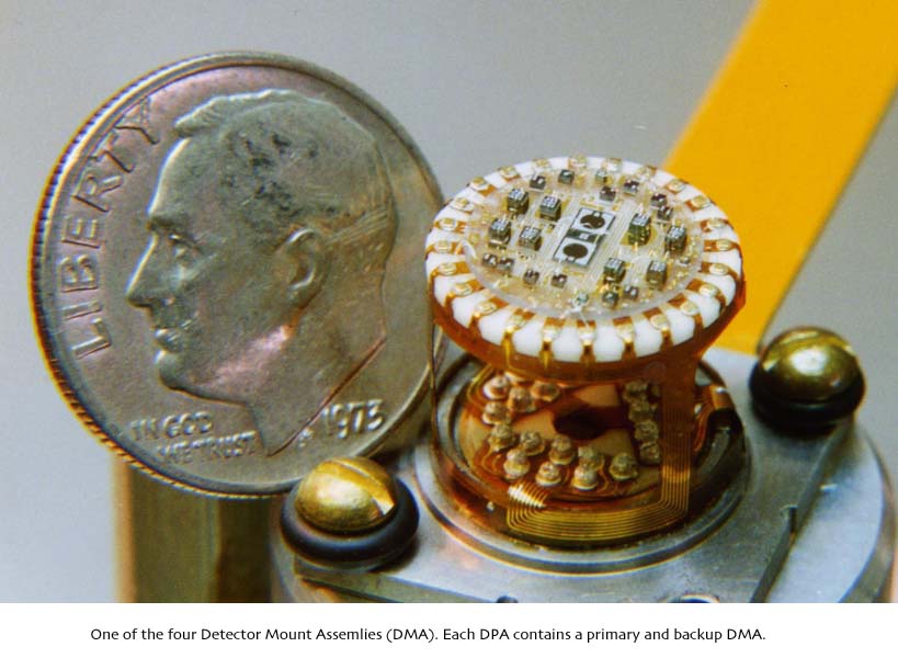
Each pair of D-half spots is then focused onto two tiny sensors in the center of the DMA (each sensor is about the size of Roosevelt's eye on a dime). When the sensors detect light, we know that the telescope is pointed at the guide star. When the two sensors see exactly the same amount of light, we know that the telescope is pointed at the center of the guide star. With averaging, this method allows us to achieve alignment accuracies better than a milli-arc-second (less than 1/3,600,000 of a degree).
During any portion of each orbit when the earth is between the spacecraft and the guide star, these telescope sensors are not used. Whenever the guide star comes into view of the telescope, the output from the X-axis and Y-axis DMA sensors is fed to the spacecraft’s Attitude and Translation Control system (ATC), which rapidly locks onto the guide star. The ATC continually adjusts the spacecraft’s pointing direction so that the DMA readings from both halves of the respective X-axis and Y-axis beams are equalized, thus ensuring that the telescope remains directly centered on the guide star in both the X and Y axes.
Drawings & photos: The diagram of the GP-B experiment, the diagram of the telescope beam path, and the DMA photo are all from the GP-B Image Archives here at Stanford. All of the other telescope photos were taken by GP-B Public Affiars Coordinator, Bob Kahn. Click on the thumbnails to view these images at full size.
Please Note: We will continue updating these highlights and sending out the GP-B email update on a weekly basis—at least through the first few weeks of the Science Phase of the mission. As mission operations become more routine, we may reduce the frequency of these updates to biweekly. However, from time to time, we intend to post special reports and special updates, as warranted by mission events.
SWISS AMATEUR ASTRONOMER PHOTOGRAPHS GP-B GP-B SPACECRAFT IN ORBIT WITH GUIDE STAR IM PEGASI
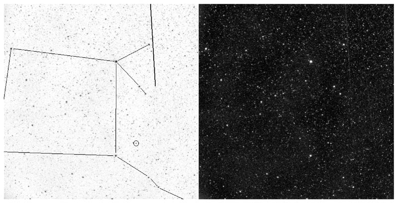
To the right, is a thumbnail of a photograph of the GP-B spacecraft in orbit, along with the guide star, IM Pegasi. (Click on the thumbnail to view the photo at full size.) The photo was taken and emailed to us by Stefano Sposetti, a Swiss physics teacher and amateur astronomer. Stefano used a 40cm newtonian telescope, with a CCD camera and 20mm wide field lens attached to make this photo. He then sent us the two versions shown — the normal (black sky) version on the right, and an inverse version in which the constellation, Pegasus, the guide star IM Pegasi, and the path of the GP-B spacecraft are highlighted for easy identification on the left.
We are grateful to Stefano for sending us this wonderful photo. You can view other astronomical photos that he has taken on his Web page: http://aida.astronomie.info/sposetti. Following is Stefano's description of his photo:
In this picture one can see the quite dim GP-B satellite traveling from North (up) to South (down) direction. The bold line in the right part of the left image represents the satellite trail just before entering the earth shadow. (Every satellite becomes visible because it reflects the sunlight). The connecting lines show the constellation Pegasus. The small circle around the star is IM Pegasi, the guide star used by the spacecraft's telescope in his experiment! GP-B is a circumpolar satellite following a free fall trajectory about 640km above the earth surface. From my location the satellite passed that night at a maximum elevation of 87degrees, thus not exactly overhead. The brightness of the satellite was between 3mag and 4mag. The Moon, about in the last quarter phase, illuminated the sky and was a drawback for having a good signal/noise ratio of the satellite trace. I took this 60-seconds black and white CCD picture with a 20mm,f/2.8 lens on august 6 centered at 01:19:00 UT. North is up, East is left.
More links on recent topics
- Track the satellite in the sky
- Photo, video & and news links
- Build a paper model of the GP-B Spacecraft
- Following the mission online
- Our mailing list - receive the weekly highlights via email
- The GP-B Launch Companion in Adobe Acrobat PDF format. Please note: this file is 1.6 MB, so it may take awhile to download if you have a slow Internet connection.
Previous Highlight
Index of Highlights