WEEKLY UPDATE FOR 1 JULY 2005:
GRAVITY PROBE B MISSION STATUS AT A GLANCE
| Item | Current Status |
| Mission Elapsed Time | 437 days (62 weeks/14.32 months) |
| Science Data Collection | 308 days (44 weeks/10.10 months) |
| Current Orbit # | 6,449 as of 3:00 PM PST |
| Spacecraft General Health | Good |
| Roll Rate | Normal at 0.7742 rpm (77.5 seconds per revolution) |
| Gyro Suspension System (GSS) | All 4 gyros digitally suspended in science mode |
| Dewar Temperature | 1.82 kelvin, holding steady |
| Global Positioning System (GPS) lock | Greater than 97.3% |
| Attitude & Translation Control (ATC) | X-axis attitude error: 237.2 marcs rms |
| Command & Data Handling (CDH) | B-side (backup) computer in control Multi-bit errors (MBE): 1 (in GSS computer on 6/30) Single-bit errors (SBE): 15 (daily average) |
| Telescope Readout (TRE) | Nominal |
| SQUID Readouts (SRE) | Nominal |
| Gyro #1 rotor potential | +2.2 mV |
| Gyro #2 rotor potential | +2.1 mV |
| Gyro #3 rotor potential | +7.9 mV |
| Gyro #4 rotor potential | +2.2 mV |
| Gyro #1 Drag-free Status | Backup Drag-free mode (normal) |
MISSION DIRECTOR'S SUMMARY
As of Mission Day 437, the Gravity Probe B vehicle and payload are in good health. All four gyros are digitally suspended in science mode. The spacecraft is flying drag-free around Gyro #1.
This past week was relatively quiet for GP-B mission operations. Several routine adjustments were made in various spacecraft systems, and preliminary instrument calibration tests are continuing.
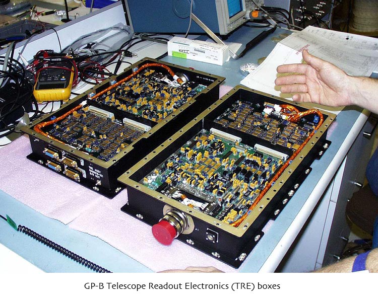
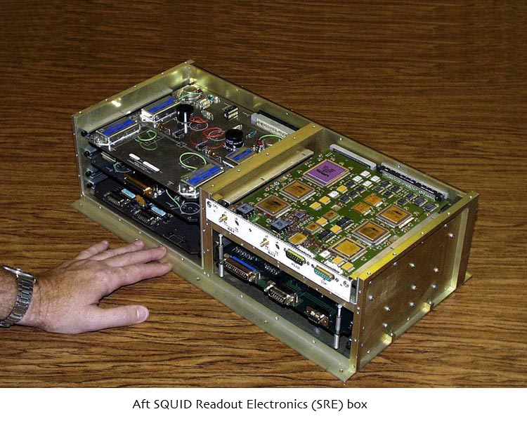
During the mission up to this point, we have been cycling certain applications on and off in the SQUID Readout Electronics (SRE) and Telescope Readout Electronics (TRE) computers during Guide Star Valid (GSV) and Guide Star Invalid (GSI) periods to ensure that these computers have adequate margin for memory scrubbing, which automatically corrects single-bit errors (SBEs). Based on recent engineering tests, we have determined that leaving these applications on all the time, instead of cycling them on and off, doubles the length of the memory scrub period, which doubles the likelihood of these computers sustaining a multi-bit error (MBE) composed of two SBEs in a single memory word during a scrub cycle. However, based on the engineering tests and on-orbit experience, we have determined that the probability of sustaining an MBE composed of two SBEs was deemed to be an acceptable level of risk. The advantage of keeping these applications enabled all the time is that it provides simultaneous data on trapped flux and the London moment, in addition to the science pointing (relativity) data.
On Wednesday 29 June 2005, members of our Anomaly Review Board presented information about our GP-B anomaly review process to a NASA group studying anomaly resolution best practices at NASA's Ames Research Center here in Mountain View, CA.
On Thursday, 30 June 2005, a multi-bit error (MBE) occurred in a benign location in the Gyro Suspension (GSS) computer for gyro #2. This memory location was subsequently patched, restoring its proper value.
MISSION NEWS—The GP-B MICRO THRUSTERS: PRECISION POINTING & DRAG FREE FLIGHT
Continuing our mission news stories on interesting GP-B technologies, based on the final report we are compiling for NASA, this week we describe the GP-B micro thruster system. Many thanks to GP-B students Mark McCauley and Brandon Owens for providing major sections of this story.
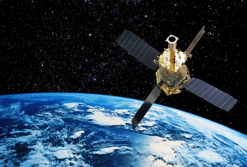
GP-B is the first spacecraft ever launched with a requirement to control six degrees of freedom in the spacecraft's motion: three degrees of attitude control (pitch, yaw, and roll), as well as three degrees of translational drag-free control (forward-back, side-to-side, and top-to-bottom). Many other spacecraft, like the Hubble Space Telescope, control pitch and yaw, but they do not control roll. Also, GP-B is only the second satellite ever launched to achieve full 3-axis drag-free control.
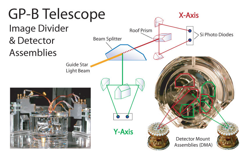
Two axes of attitude control (pitch and yaw) are necessary in order for the telescope to lock onto the guide star, IM Pegasi, providing the reference orientation for measuring the relativistic drift of the gyro spin axes. As we've described in the weekly news stories dated 5 November 2004 and 6 May 2005, the GP-B telescope uses a half-silvered mirror to divide the incoming light beam from the guide star into X-axis and Y-axis component beams, each of which are then split with prisms into two half-beams. Two sets of photon detectors (plus two redundant sets) in each axis provide feedback to the spacecraft's thrusters for keeping the telescope precisely centered on the guide star beam in both the X-axis and Y-axis. The thrusters are also used to maintain the spacecraft's constant roll rate of 0.7742 rpm (77.5 seconds per revolution) along the Z-axis--the main axis of the spacecraft and telescope.
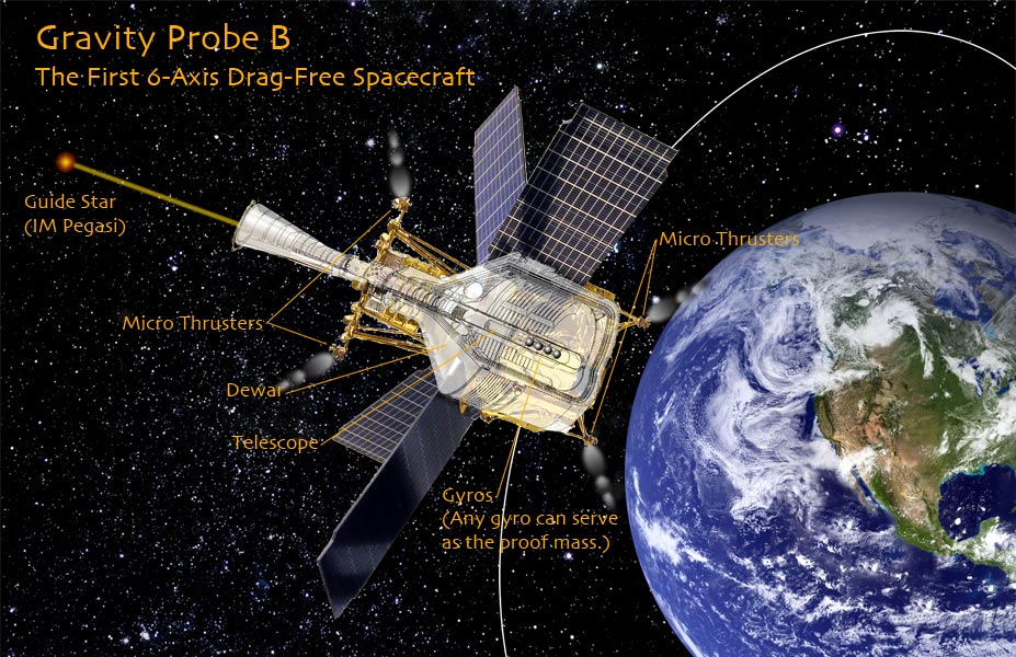
As noted above, the thrusters are also used to control the GP-B spacecraft drag-free in its orbit. In a typical drag-free spacecraft, a spherical “proof mass” is suspended in a housing inside the main spacecraft--a satellite within a satellite. The housing for the proof mass contains sensors that measure its position relative to the main spacecraft. Positional feedback from the proof mass housing is then used to control small thrusters on the main spacecraft, so that the proof mass always remains centered in its housing. In other words, the thrusters continually adjust the position of the spacecraft so that the proof mass inside remains in a constant state of free fall.
In the case of the GP-B spacecraft, any of the science gyros can serve as the proof mass. (During most of the science phase of the mission gyro #3 has been serving as the proof mass, but we recently switched to gyro #1 for calibration purposes.) Because the proof mass is located inside the main spacecraft, it is protected from atmospheric drag, solar radiation, and other such disturbances--thus, the name “drag-free.” Any drag on the main spacecraft is nullified by the thrusters, and thus the orbital path of the proof mass is determined only by gravity and some insignificant forces from the main spacecraft itself.
When you think of spacecraft thrusters, an image of the large cone-shaped nozzles at the base of a rocket or the nozzles on the back of the Space Shuttle may come to mind. Large thrusters like these are required to lift a gigantic rocket and its heavy payload off the ground and break free of Earth's gravity or even to change the Shuttle's orbital position for re-entry. However, even though the GP-B spacecraft is as large as a medium-sized school bus and weighs a couple of tons here on Earth, once in orbit, the forces required to keep the GP-B telescope locked onto the guide star or to maintain a drag-free orbit are minute, and they require a much smaller and precise type of thruster. In fact, the thrusters aboard the GP-B spacecraft are more akin to “controlled leakers” than thrusters, and thus they are called “micro thrusters.”
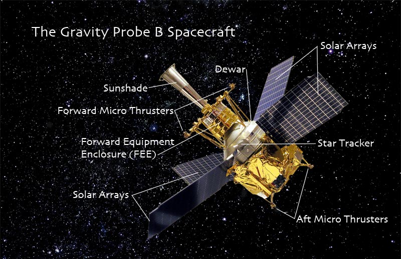
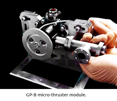
The GP-B spacecraft is equipped with 16 micro thrusters, arranged in four clusters, each containing two pairs of opposing thrusters. Two of the clusters are mounted at opposite corners of a plate that caps the Forward Equipment Enclosure (FEE) surrounding the top of the probe, where the conical sunshade joins the probe's cross flange. The other two clusters are located towards the ends of opposing struts at the bottom of the spacecraft frame. These thrusters use helium gas, vaporized from liquid helium that “sweats” out through the Dewar's porous plug, as a constant source of propellant. (The Dewar's cryogenic cooling system and the porous plug are interesting technologies in their own right, and we will discuss them in a future Mission News story.)
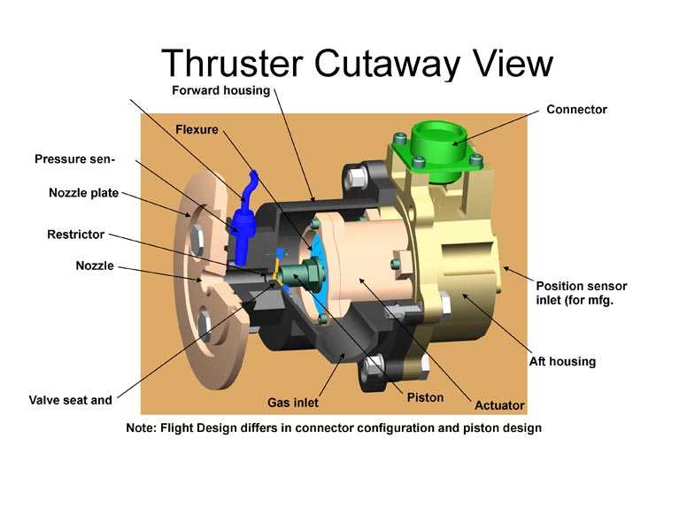
The flow of helium gas evaporating from the surface of the porous plug is first directed through the Dewar's vapor-cooled shields, and then out to the thruster system. Each thruster has an actuator, composed of a spring-loaded diaphragm that regulates the thruster's output into metered “puffs” of helium gas. In this way, the position and pointing of the spacecraft can be precisely controlled.

Since the amount of helium sweating out of the Dewar is on the order of milligrams per second (mg/s), each thruster can only impart a tiny force on the vehicle. Specifically, each thruster has an estimated maximum output force of eight milliNewtons (8mN) using 6.9 mg/s of helium. A couple of examples will help put these numbers into perspective. A baseball weighs approximately 1.4N (5oz). This means that more than 175 micro thrusters placed directly beneath the baseball would be required to lift it off the ground. A golf ball weighing approximately 0.45N (1.6oz) would need 57 micro thrusters to lift it off the ground. A marble weighing 0.03N (0.1oz) would still require 4 micro thrusters to support its mass.
The amount of thrust produced by each thruster can be regulated linearly. Ground testing has revealed a directly proportional relationship between thrust and pressure in the restrictor of each thruster. Pressure in the restrictor is controlled by movement of a piston and measured by a piezoresistive type transducer sensor, with a range from 0 pounds per square inch (psi) to 1 psi--equivalently, 0 millimeters of Mercury (mmHg or torr) to 51.706 torr. The output of the pressure transducer as read by the onboard computer and sent to the ground through telemetry is measured in milliVolts (mV). Each mV measured by the sensor roughly corresponds to a range of 0.20684 - 0.34473 torr. An analysis of thruster data collected throughout the mission indicates that the thrusters can consistently control the restrictor pressure to a reading of 1.4 mV, which corresponds to less than 1 mN of thrust.
Very early in the mission, two of the thrusters--thruster #6 and thruster #8--malfunctioned and were isolated (closed off) from the system. On 21 April 2004, thruster #6 was reporting a high pressure, and all attempts to regulate it failed. In examining the data plots from this thruster, no correlation could be found between its current and pressure. Thus, we concluded that the nozzle of thruster #6 was stuck open by particle contamination, and we isolated it from the system.
Then, on 17 May 2004, thruster #8 was resisting attempts to modulate its helium flow. Although its pressure-current correlation appeared nominal, the spacecraft was having difficulty locking on to the guide star. Through a process of fault tree analysis, we determined that Thruster #8 was the source of this problem, and that once again, particle contamination was the cause. We thus isolated thruster #8 from the system, and the guide star lock-on times returned to their nominal range.
The GP-B micro thruster system was designed with geometrical and internal redundancies that allow up to four individual thrusters to fail without decreasing control performance. Thus, the malfunction of two thrusters shortly after launch had no detrimental effect on the overall mission. However, the isolation of these two thrusters warranted the uploading of revised control software in order to optimize performance with 14 instead of 16 micro thrusters. The upload of the revised thruster software was completed on 25 June 2004.
At launch, all of the thrusters were set to use a closed loop bias, where the on-board computer updated the current to match the required pressure. However, due to radiation and algorithm errors detected during the IOC phase of the mission, thrusters #1 and #7, were switched to an open loop bias, which can only be changed by commands sent to the spacecraft from the GP-B Mission Operation Center (MOC). The thruster bias is updated when necessary, which keeps the thruster pressure from becoming erratic due to drift caused by solar radiation and algorithm error. The bias also keeps the thrusters complementing each other, so that the roll rate stays perfectly constant.
By the end of the IOC phase of the mission, the thruster system was completely tuned up, and it has performed nominally throughout the science phase of the mission.
UPDATED NASA/GP-B FACT SHEET AVAILABLE FOR DOWNLOADING
We recently updated our NASA Factsheet on the GP-B mission and experiment. You'll now find this 6-page document (Adobe Acrobat PDF format) listed as the last navigation link under "What is GP-B" in the upper left corner of this Web page. You can also click here to download a copy.
Drawings & Photos: The layered composite photo of the GP-B spacecraft orbiting the Earth, as well as the diagrams of the telescope, drag-free spacecraft, and spacecraft parts were created by GP-B Public Affairs Coordinator, Bob Kahn using Adobe Photoshop and Adobe Illustrator. The photos of the SRE & TRE electronics boxes, as well as the photos and cutaway diagrams of the micro thrusters are courtesy of Lockheed Martin Corporation. Click on the thumbnails to view these images at full size.
MORE LINKS ON RECENT TOPICS
- Track the satellite in the sky
- Photo, video & and news links
- Build a paper model of the GP-B Spacecraft
- Following the mission online
- Our mailing list—receive the weekly highlights via email
- The GP-B Launch Companion in Adobe Acrobat PDF format. Please note: this file is 1.6 MB, so it may take awhile to download if you have a slow Internet connection.
Previous Highlight
Index of Highlights