WEEKLY UPDATE FOR 3 JUNE 2005:
GRAVITY PROBE B MISSION STATUS AT A GLANCE

| Item | Current Status |
| Mission Elapsed Time | 409 days (58 weeks/13.40 months) |
| Science Data Collection | 280 days (40 weeks/9.18 months) |
| Current Orbit # | 6,036 as of 5:00 PM PST |
| Spacecraft General Health | Good |
| Roll Rate | Normal at 0.7742 rpm (77.5 seconds per revolution) |
| Gyro Suspension System (GSS) | All 4 gyros digitally suspended in science mode |
| Dewar Temperature | 1.82 kelvin, holding steady |
| Global Positioning System (GPS) lock | Greater than 96.0% |
| Attitude & Translation Control (ATC) | X-axis attitude error: 245.9 marcs rms |
| Command & Data Handling (CDH) | B-side (backup) computer in control Multi-bit errors (MBE): 2 (in SRE computer on 5/30) Single-bit errors (SBE): 7 (daily average) |
| Telescope Readout (TRE) | Nominal |
| SQUID Readouts (SRE) | Nominal |
| Gyro #1 rotor potential | -0.2 mV (As of 5/26) |
| Gyro #2 rotor potential | -1.0 mV (As of 5/26) |
| Gyro #4 rotor potential | -0.7 mV (As of 5/26) |
| Gyro #3 Drag-free Status | Backup Drag-free mode (normal) |
MISSION DIRECTOR'S SUMMARY
As of Mission Day 409, the Gravity Probe B vehicle and payload are in good health. All four gyros are digitally suspended in science mode. The spacecraft is flying drag-free around Gyro #3.
Late last Thursday, Gyro #2 transitioned from its normal digital suspension to analog backup suspension mode. This gyro was re-suspended in digital mode last Saturday, 28 May 2005, and it has remained digitally suspended since that time. The root cause of this transition is still under investigation.
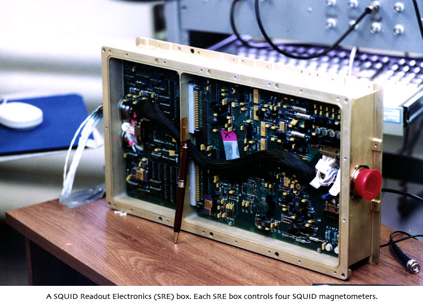
Last Sunday, 20 May 2005, the SQUID Readout Electronics (SRE) computer experienced two multi-bit errors (MBEs). One of these errors was located in a data buffer location that cleared itself, thus removing the error. The second error was located in a section of program code that is not planned for use. In response, the Mission Operations team has since removed this code module from the computer's database, so that it cannot be accessed inadvertently.
Various planned preliminary calibration tests are continuing, including some tests of Gyro #3 and the drag-free system. Such tests are standard operating procedure on experimental missions. During these tests, we purposely vary certain parameters that would not be expected to change greatly during the experimental portion of the mission for the purpose of characterizing instrument component performance. In order to maximize the length of the science data collection phase of the GP-B mission, we are currently running some preliminary calibrations that can safely be performed while we are still collecting science data. Our final calibration tests, which must be completed before the helium in the Dewar is depleted, involve placing torques (forces) on the gyros, so we can only perform these tests after data collection is finished—early in August.
MISSION NEWS—THE GP-B PROBE'S REALLY COOL WINDOWS: Part I
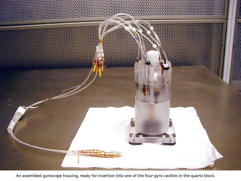
Note: This week's GP-B Mission News story is too long to cover in one update, so we've divided it into two parts. We will post Part II next week.Consider the following: GP-B's four gyroscopes are mounted in a quartz
block, which is suspended near the bottom of a 9-foot long vacuum chamber,
shaped like a cigar tube and called “the probe.” The probe is
mounted along the central axis of the Dewar, surrounded by a bath of superfluid
helium, maintained at a temperature of 1.8 Kelvin (-456 degrees Fahrenheit).
Sitting on top of the quartz block and monolithically bonded to it is the
telescope.
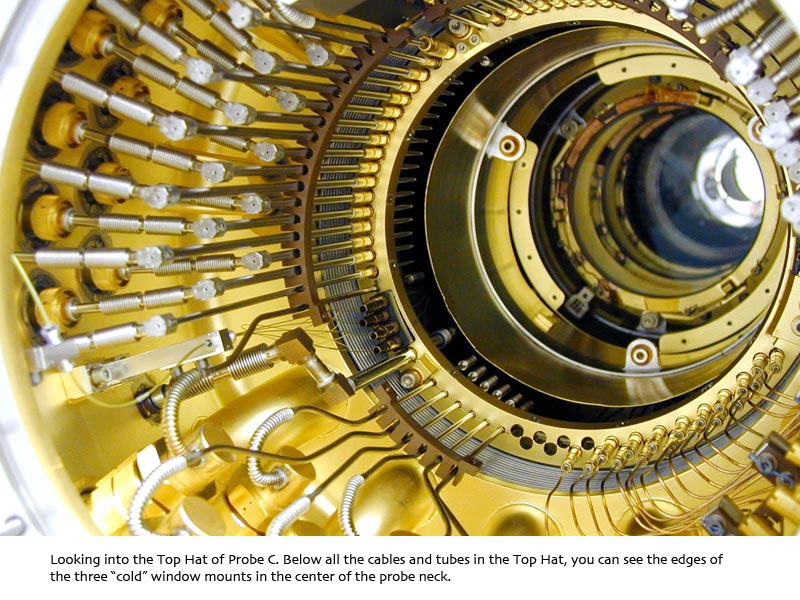
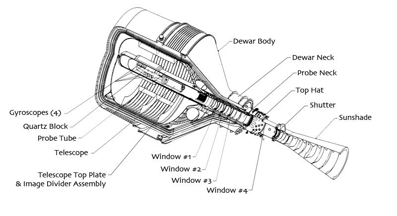 Above the telescope, the cylindrical probe wall rises about three
more feet into the neck of the Dewar, ending at the "Top Hat," which
caps off the Dewar and the probe. The Top Hat provides an interface for over
400 cables and tubes that connect various parts of the science instrument
(gyros and telescope) inside the probe with the many electronics boxes, computers,
and pure helium gas for spinning up the gyros that are all mounted in the
bays of the spacecraft frame and the Forward Equipment Enclosure (FEE) surrounding
the Top Hat.
Above the telescope, the cylindrical probe wall rises about three
more feet into the neck of the Dewar, ending at the "Top Hat," which
caps off the Dewar and the probe. The Top Hat provides an interface for over
400 cables and tubes that connect various parts of the science instrument
(gyros and telescope) inside the probe with the many electronics boxes, computers,
and pure helium gas for spinning up the gyros that are all mounted in the
bays of the spacecraft frame and the Forward Equipment Enclosure (FEE) surrounding
the Top Hat.
Light from the guide star, IM Pegasi, must be able to shine down through the Top Hat, into the probe, and ultimately into the telescope. Thus, the probe needed to have some kind of window system that would allow starlight from IM Pegasi to pass into the telescope, while keeping infrared and microwave radiation (heat energy) out and maintaining an ultra-high vacuum and ultra cold environment inside the probe. There also had to be some way of blocking extraneous light from the sun that could burn out the sensitive photon detectors in the telescope.
Furthermore, in order to be tested prior to launch, this window system had to work here on earth, where the differential between the pressure and temperature inside and outside the probe is far greater than in space. In addition, this probe window system needed to:
- Remain virtually free of condensation and contamination.
- Avoid creating extraneous reflections between windows.
- Maintain the vacuum seal inside the probe.
- Withstand the pressure and temperature on the outermost window, which could cause significant lensing or bulging that would distort the starlight from the guide star.
 Needless to say, designing and building such a system of windows inside the
probe turned out to be another of GP-B's formidable engineering challenges.
Needless to say, designing and building such a system of windows inside the
probe turned out to be another of GP-B's formidable engineering challenges.
Over the years, three probes, labeled A, B, and C, were constructed, each improving on the previous one. Probe C is the flight probe on-board the spacecraft. Probe B currently sits on a stand outside the conference room where we hold our daily status briefings, and Probe A is in an off-site storage facility.
The window system that evolved consists of four circular windows--three inside the probe and one hermetically sealed on the end of the probe. Above the end window, a conical sunshade extends several feet to the top of the spacecraft. The inside of the sunshade is lined with baffles that absorb and redirect stray light from the sun. A shutter at the bottom of the sunshade can be closed to prevent any light from entering the probe or telescope. The sunshade and shutter address the issue of sunlight entering the telescope and burning out its photon detectors.
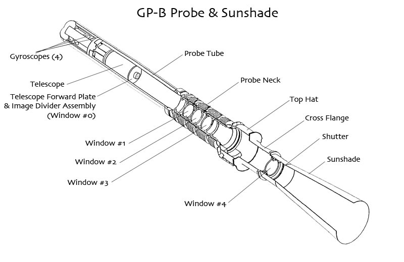
The three windows inside the probe are numbered from #1, closest to the telescope, to #3 further up the tube. Window #4 forms the vacuum seal at the end of the probe, above the Top Hat. Window #4 has a number of special requirements and characteristics that will be described in next week's update. The three inner windows are about 6 1/2" in diameter, with 6" clear aperture. They are made of fused quartz--the same material used to make the quartz block, gyros and housings, and the telescope, and they have anti-reflective coatings, not unlike the coatings used on eyeglasses, that minimize reflections off the window surfaces and block infrared light, while allowing visible light to pass through. In fact, these coatings provide increased visible light transmission over uncoated glass. In addition to enabling the light from the guide star to reach the telescope, the other main purpose of these windows is to successively dissipate all of the heat entering the probe through three copper heat-exchange stations that are thermally connected to four successive layers of heat exchangers that line the Dewar's outer shell.

The lower portion of the probe, which resembles a cigar tube, is suspended from the neck tube of the Dewar. Its cylindrical shell is made of aluminum, which conducts the cryogenic temperature of the liquid helium surrounding it to the science instrument assembly (telescope and gyros) inside. Above the telescope, the material comprising the cylindrical shell of the probe's neck tube changes from aluminum to a gamma alumina ceramic composite. The upper composite probe shell is joined to the lower aluminum shell with an O-ring seal of epoxy and Indium, a very soft metallic element that remains soft at low temperatures. The composite material comprising the upper shell of the probe, where the windows are located, is a very low thermal conductor, so that it does not pass heat down into the lower portion of the probe, which must remain at the cryogenic temperature of 1.8 K.


Moving up the cylindrical probe wall from the telescope, the three inner windows are mounted in thermal conducting copper brackets that are attached to the first three of four thermal platforms. These platforms are strategically spaced along the upper portion of the probe, so that they connect to four successive heat exchanger layers of the Dewar shell that terminate in the Dewar neck. Each thermal platform consists of a pair of copper bands, one inside the probe wall, with a matching band at the same location on the outside of the probe wall. The inner bands were first frozen with liquid nitrogen, inserted into their correct positions inside the probe, heated so that they expanded to fit tightly against the inner probe wall, and then glued into place with epoxy. The outer bands were positioned outside their inner probe counter parts and shrunk for a tight fit against the outer probe wall and likewise glued into place with epoxy. Thus, each heat platform is comprised of a sandwich of copper bands, conducting heat from the inner band through the thin probe wall to the outer band. In turn, the outer bands of the probe's thermal platforms each touch, and thus conduct the heat to a copper ring in the Dewar neck, corresponding to one of the Dewar's four successive heat exchanger layers.

As an interesting historical note, the thermal conduction from the inner copper band through the probe wall to the outer copper band worked quite well in Probe A and Probe B. However, for some reason, when these thermal platform band assemblies were completed in the final Probe C, the thermal conduction through the probe wall was significantly diminished. At this stage in the development of Probe C, it would have taken years to redesign and fabricate a new probe with the proper heat exchanger for the windows. Fortunately, Lockheed Martin Lead Designer, Gary Reynolds, collaborating with GP-B Co-Principal Investigator, John Turneaure, now an Emeritus Professor of Physics at Stanford, came up with a work-around solution that saved the probe: they decided to drill small holes through the outside copper bands, through the probe wall, and into the inner band…but not all the way through the inner band, which would destroy the vacuum inside the probe. Then, they inserted copper dowels into these holes and glued them in place with a special epoxy. The epoxied copper dowels established a strong thermal connection from the inner bands to the outer bands, as well as ensuring that the vacuum seal inside the probe remained intact.
Next week, in Part II of this story, we will talk about Window #4, which has its own special set of requirements. We will also describe how the whole system works, including the temperature differentials at each successive thermal platform and the successive loss of light from the guide star, as it passes through some 24 optical surfaces on its way to the telescope's photon detectors.
UPDATED NASA/GP-B FACT SHEET AVAILABLE FOR DOWNLOADING
We recently updated our NASA Factsheet on the GP-B mission and experiment. You'll now find this 6-page document (Adobe Acrobat PDF format) listed as the last navigation link under "What is GP-B" in the upper left corner of this Web page. You can also click here to download a copy.
Drawings & Photos: Tthe composite photo showing the GP-B spacecraft in orbit above the Earth was created with Adobe Photoshop by GP-B Public Affairs Coordinator, Bob Kahn.The schematic diagrams of the GP-B Dewar and probe, and the photos of the gyro housing, SRE box and all of the probe photos are from the GP-B Image Archive here at Stanford University. The photos of the flight backup inner probe windows were taken by Bob Kahn and Ken Bower. Click on the thumbnails to view these images at full size.
MORE LINKS ON RECENT TOPICS
- Track the satellite in the sky
- Photo, video & and news links
- Build a paper model of the GP-B Spacecraft
- Following the mission online
- Our mailing list—receive the weekly highlights via email
- The GP-B Launch Companion in Adobe Acrobat PDF format. Please note: this file is 1.6 MB, so it may take awhile to download if you have a slow Internet connection.
Previous Highlight
Index of Highlights