GP-B Gyro #1 Polhode Motion Animations
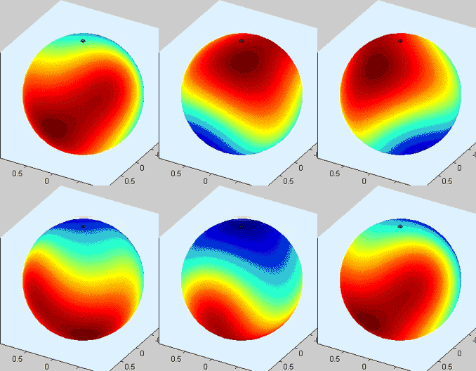
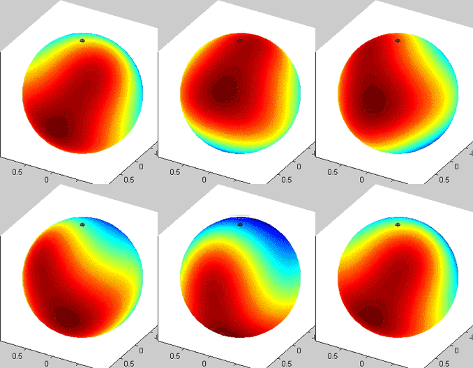
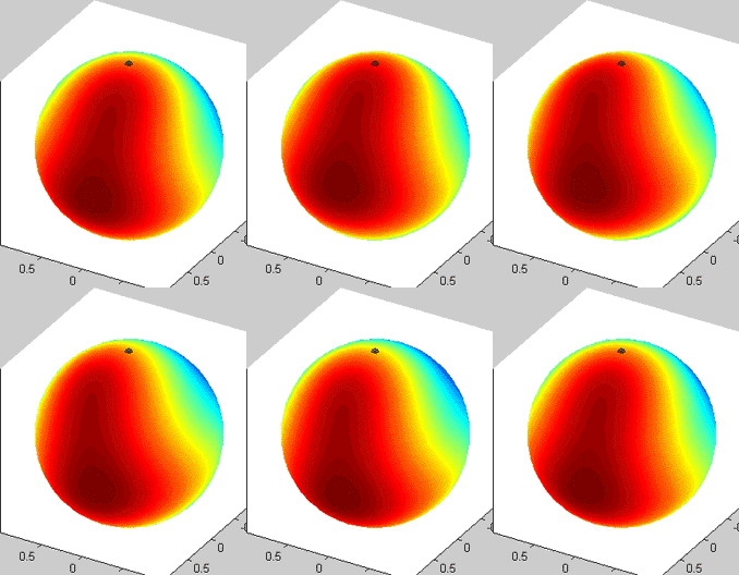
The three animations below were created from actual data for gyro #1. They display a complete polhode path at three time periods in the flight mission. The path in each animation is shown as a sequence of snapshots, taken at the gyro spin frequency. In other words, imagine that a strobe light is flashed and a snapshot of the rotor's orientation taken once per revolution as the rotor traces out one complete polhode path. (Note: these animations are set to loop continuously, so the motion on each path is being repated over and over again.)
| Early Mission | Mid Mission | Late Mission |
|---|---|---|
 |
 |
 |
| Large Polhode Path | Moderate Polhode Path | Very Small Polhode Path |
The color on the animated gyro rotor is essentially a topographical surface map of the rotor's surface, as measured by the Gyro Suspension Sytem and SQUID readout on orbit. The red areas represent the highest points on the surface; the blue areas are the lowest, with the yellow-green areas in between. If the rotor were actually painted in this rainbow-colored pattern, it would show this motion under a strobe light flashing once per revolution. The small, fixed hole on the top of each animated rotor represents the axis around which the rotor is spinning—that is, the gyro's spin axis.
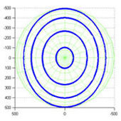
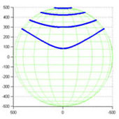
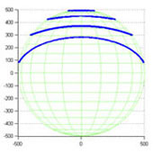
Notice that the spin axis is fixed in its vertical position, while the rotor's orientation changes continually. If the strobe light were turned off, you would see a blur of color as the rotor rotates around its fixed spin axis. Furthermore, If a pen were placed in the small spin-axis "hole," just touching the rotor surface, it would trace out the polhode path on the rotor. The series of plots below shows the changing polhode path of gyro #1 from early in the mission (large path) to late in the mission (very small path).
| Changing Polhode Paths on Gyro #1: Large Path=early mission; Small Path=late mision | |||
|---|---|---|---|
 |
 |
 |
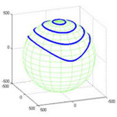 |
| Top View | Front View | Side View | Perspective View |
