

June 11, 2007 - The Two Surprises and Their Underlying Cause
TIME-VARYING POLHODE MOTION IN THE GYRO ROTORS
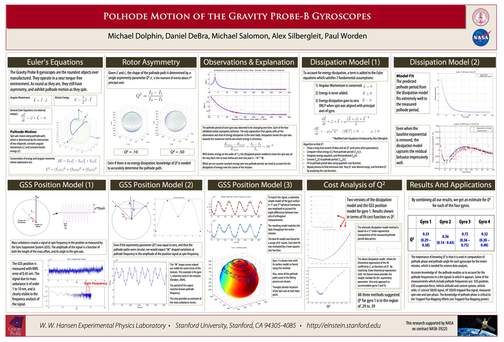
A brief overview of polhode motion in the gyro rotors
The gyroscope's polhode motion is akin to the common "wobble" seen on a poorly thrown (American) football, though it shows up in a much different form for the ultra-spherical GP-B gyroscopes. While it was expected that this wobble would exhibit a constant pattern over the mission, it was found to slowly change due to minute energy dissipation in the spinning gyro rotors, caused by interactions of electrostatic patches on the rotor's surfaces and patches on the metallic surfaces inside the housings. The polhode wobble complicates the measurement of the relativity effects by putting a time-varying wobble signal into the data.
- For a complete discussion of polhode motion, see the GP-B Mission News story entitled: Polhode Motion in the GP-B Gyroscopes in the 20 November 2006 GP-B update.
The effects of time-varying polhode motion on the GP-B experiment
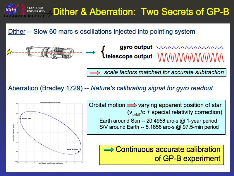
As noted in the Next Steps section of our GP-B Home page, both the SQUID-based magnetic measurement (London moment) of the gyro spin axes and the telescope measurement of the spacecraft pointing direction with respect to the guide star produce electrical signals that represent angular measurements. Because these two systems are independent of each other, it is necessary to cross-calibrate these instruments to ensure that both systems are measuring the same relative angle when the orientation of the spacecraft changes.
Fortunately, the GP-B experimental data includes natural calibrating signals in the form of the aberration of starlight—both orbital and annual. Our goal is to perform this calibration to a precision of 1 part in 100,000 (0.001 percent), but our measurements are limited by the noise in our SQUID readout system. If there were no variation in the polhode period of the gyros, we could simply string together the data taken during the Guide Star Valid (GSV) portion of each orbit (when the spacecraft has a direct line of sight to the Guide Star) from a sequence of orbits until we have reached the desired 0.001 percent precision. (We must string together data from ~15 orbits to reach this level of precision.) However, the polhode periods for the gyros did vary over the data collection period, and this makes it much more difficult to connect the data from successive orbits.
The complication is due to the presence of a residual magnetic flux that becomes trapped on the gyro rotors when they are cooled to superconductive temperatures. Whereas a constant polhode period can easily be removed, a varying polhode period must be precisely modeled for each orbit before it can be removed. Consider three cases:
-
London moment with varying polhode rates and no trapped magnetic flux—In this case, there is no problem; the data from successive orbits can easily be strung together to yield the desired precision since the London Moment is independent of rotor polhode dynamics to the levels we hope to measure.
-
London moment with 1% trapped magnetic flux, but constant polhode period (no variation)—Again, in this case there is no problem; the data from successive orbits can still be strung together because the constant polhode period clearly stands out from other signals as the data analysis proceeds. Thus, it can be precisely separated and removed.
-
London moment with both trapped magnetic flux and time-varying polhode rates—This situation, which we have determined is the case for the GP-B gyros, requires very precise modeling of the polhode motion for each gyro. Initial modeling that was based on information from the primary science readout gave reasonable results, but it lacked a detailed dynamic model of the polhode motion. Now, some GP-B graduate students are working on a method that uses high-rate SQUID data “snapshots” to map out the trapped flux patterns on each gyro. Using this map, together with a rotor dynamic model, we can more accurately predict the effect of rotor trapped flux on the gyro readout calibrations. Moreover, with accurate trapped flux maps, we can string together relativity data from successive orbits to achieve the desired experimental precision. Once we have the trapped flux modeling, the fitting process becomes much easier.
CLASSICAL MISALIGNMENT TORQUES ON THE GYROS
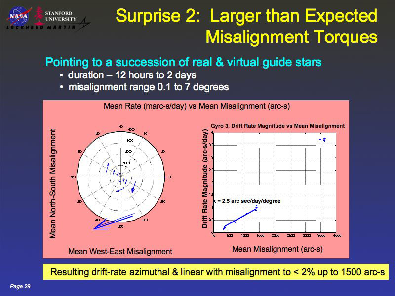
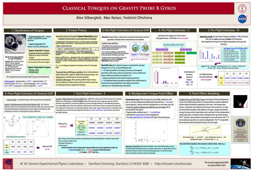
After months of research and analysis, our GP-B science team has determined that electrostatic patches are also the cause of the small torques we have observed on the gyroscopes when the spacecraft's axis of symmetry is not aligned with the gyroscope spin axes. Torques cause the spin axis of a gyroscope to change orientation, and in certain circumstances, this effect can look like the relativity signal GP-B measures. Fortunately, the change in gyro spin axis orientation due to these torques has a precise geometrical relationship to the misalignment of the gyro spin/vehicle symmetry axis, and thus effects of these so-called misalignment torques can be removed from the data without directly affecting the relativity measurement.
Important data that has enabled us to understand and model these torques was collected during a series of planned instrument calibration tests that we conducted during the final six weeks of the flight mission, from mid-August through the end of September 2005, when the helium in the dewar was finally exhausted. During these calibration tests, we purposely slewed the spacecraft and telescope from the guide star, IM Pegasi, to observe other stars nearby for 12 to 24 hours, and then returned to IM Pegasi. These exaggerated mis-pointing maneuvers produced measurable torques on the gyros. From the results of these tests, the team has been able to determine the nature and limits of these torques and has devised methods for modeling and removing them during the data analysis phase.
Our weekly mission status updates from 19 August 2005 through 30 September 2005 provide a detailed chronicle of the final calibration tests that we performed until the liquid helium in the dewar was finally exhausted. In particular, the Mission News Story dated 26 August 2005 discusses the method and purpose of post-science calibration tests.
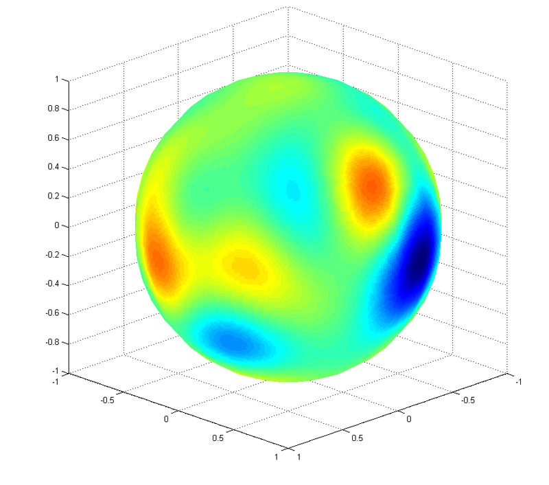
PATCH EFFECTS—THE UNDERLYING CAUSE OF BOTH SURPRISES
Perhaps the greatest and most important challenge embraced by GP-B team during the data analysis period has been to determine the underlying causes of both the unexpectedly changing polhode paths in the GP-B gyros and the misalignment torques. Data collected during the mission clearly shows that the polhode periods of all four gyros did not remain constant, but rather they damped out in all four gyros. In addition, the data also shows that the characteristic spin-down times of the gyros (the time it takes them to spin down to about 37% of their initial speed) varied from gyro to gyro, ranging from between 7,000 and 26,000 years. This result is far better than the experimental specification of 2,000 years, but it was less than initial expectations (on the order of 50,000 years). More importantly, the wide variation in spin-down rates suggests that some mechanism inherent to each individual gyro might best account for the changing polhode paths and the misalignment torques on the gyros. But what kind of mechanism could this be?
Given the almost perfectly spherical and homogeneous nature of the GP-B gyro rotors, there are two possibilities:
- Internal energy dissipation in the gyro rotors
- External torques with just the right frequency
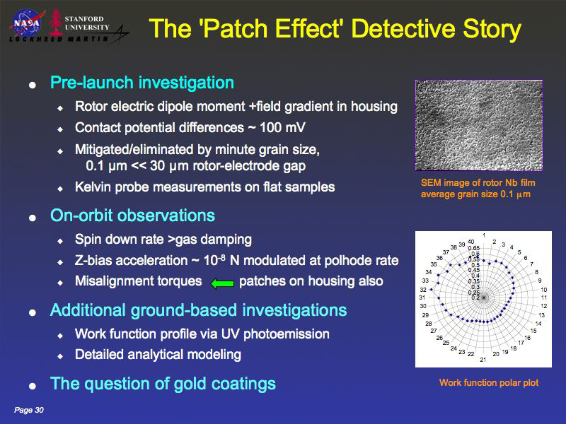
Early in the data analysis phase, we thought that some kind of internal energy dissipation was the cause. However, adding the variation in spin-down rates to the analysis, we currently believe that both mechanisms listed above are involved and that the underlying cause is "patch effect charges" on the gyro rotors and on the inside surfaces of their housings. Patch charges arise from varying surface electrical potentials in polycrystalline materials from regions of changing crystal orientations over the surface of the metal, or due to non-uniform distribution of constituent elements in a metal alloy, or can arise due to the presence of contaminants on the metal surface.
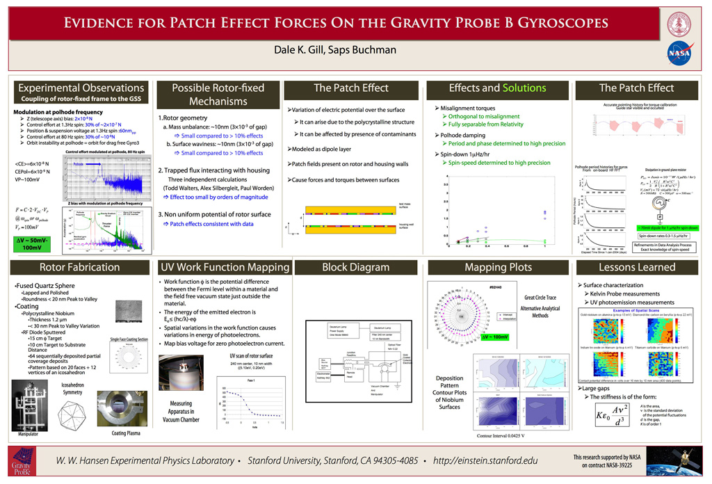
The sputtered niobium coatings on GP-B gyro rotors are naturally polycrystalline and thus inherently exhibit patch charge effects. These charges impart some potential on the six electrodes that suspend each gyro in its housing which causes a minute dissipation of energy as the rotor spins. This produces a small torque on the rotor as the energy is dissipated into the gyro housing, causing the spin rate of the gyro to slow down slightly, and also causing the polhode motion to be damped out over the mission.
We were well aware of the possible ramifications of electrostatic patches on the gyro rotors prior to launch, and we made a thorough investigation of them. In fact, a GP-B post-doctoral student carefully studied the effects of electrostatic patches on the gyro rotors and concluded that if the niobium coatings produced just two large electrostatic patches, located at opposite poles of the rotors, this would create a significant, classical torque problem in our gyros. To address this issue and determine the sizes of the patches, we performed two types of tests: 1) a visual inspection, and 2) a laboratory measurement of the size and magnitude of the patches.
The visual testing measured the grain size of the sputtered niobium coating, and found that the patches on the GP-B gyros were very small (less than 1 micrometer in size) and were scattered about the entire surface of each rotor. With such small patches randomly distributed, it was our expectation that the patch effects would average out and not be of any consequence to the experiment.
To ensure this was the case, we performed a laboratory test. We sent flat samples of niobium-coated surfaces (produced in our same Stanford lab were the gyro rotors were coated) to a lab in France where they scanned the samples with a Kelvin probe and showed that there was no problem with patches in the flat samples. (The lab in France could not handle spherical objects in their scanner, so we created flat samples using our same gyro coating machinery.)
Thus, once the spacecraft was in orbit and we began observing the changing polhode periods of the gyros and the misalignment torques, we did not initially suspect that patch effects might be the underlying cause. However, having eliminated other causes through all of the tests and calibrations performed during the mission, we have determined that patch effects are, indeed, the underlying cause of our two surprises. Furthermore, through recent gyro coating tests performed in our labs here at Stanford, we now know that we overlooked a critical issue in our method of coating the gyro rotors.
The niobium coatings on the rotors were sputtered on in a series of 64 stages, turning the rotor to a new position for each new coating. This process created a very uniform niobium coating on each rotor. However, it turns out that the final, 64th layer effectively created two large patches on the rotors, defined by its edge. In other words, the edge of the final coating essentially divides the rotor into two halves, each of which is, in fact, a large electrostatic patch at opposite poles of the rotor—the very situation that we had tested for pre-launch and had determined was “not going to be an issue.”
Knowing that this unprecedented experiment would likely uncover some surprises, we purposely collected copious spacecraft and instrument status data in addition to the scientific data and we thoroughly tested and calibrated the science instrument throughout the flight mission. This meticulous planning has paid off in many ways. For example, it has enabled our science team to develop a methodology for precisely modeling the polhode motion and trapped magnetic flux on each gyro. Most important, in the final months of the data analysis, our scientists will be able to use this modeled data to separate and remove the misalignment torques caused by these patch effects, thereby significantly improving the accuracy of the final results.