STATUS UPDATE AS OF 28 OCTOBER 2005:
GRAVITY PROBE B MISSION STATUS AT A GLANCE

| Item | Current Status |
| Mission Elapsed Time | 556 days (79.4 weeks/18.2 months) |
IOC Phase |
129 days (4.2 months) |
Science Phase |
352 days (11.6 months) |
Final Calibration Phase |
43 days (1.3 months) |
Extended Science Phase |
4 days |
Post Mission Phase |
28 days |
| Current Orbit # | 8,205 as of 5:00 PM PST |
| Spacecraft General Health | Good |
| Roll Rate | Normal at 0.4898 rpm (122.5 seconds per revolution) |
| Gyro Suspension System (GSS) | Gyros #1, #2, & #3 suspended in analog mode; gyro #4 suspended digitally |
| Gyro Spin Rates | All gyros spinning at less than 2 Hz (< 120 rpm) |
| Dewar Temperature | ~88 kelvin (and rising ~1.4 kelvin/day) |
| Global Positioning System (GPS) lock | Nominal |
| Attitude Control System (ATC) | Nominal for post-mission operation |
| Telescope Readout (TRE) | Pointing performance too low to lock onto guide star |
| Command & Data Handling (CDH) | B-side (backup) computer in control Multi-bit errors (MBE): 1 (Today in a benign location) Single-bit errors (SBE): Data Not Available |
MISSION DIRECTOR'S SUMMARY
On Mission Day 556, the Gravity Probe B vehicle and payload are in good health. All active subsystems—including solar arrays/electrical power, Experiment Control Unit (ECU), flight computer, star trackers and magnetic torque rods, gyro suspension system (GSS), and telescope detectors—are performing nominally.
The temperature in the Dewar is now at ~88 kelvin, rising at a rate of approximately 1.4 kelvin per day. The spacecraft remains in a safe configuration, and we are regularly communicating with it, monitoring the Dewar and probe as they continue to warm up.
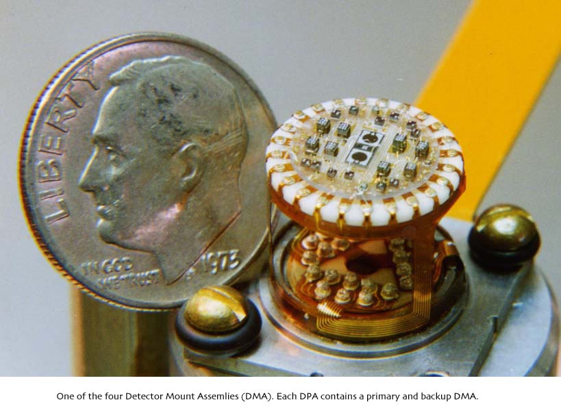
Over the past two weeks, we have periodically adjusted the telescope clamp voltages in order to keep the temperature-sensitive telescope detectors on scale. Also, we have been adjusting the internal temperature controllers in the SQUID Readout Electronics (SRE) box to maintain thermal stability. These adjustments enable us to measure changes in telescope detector noise as the ambient temperature of the probe rises. For the most part, however, we are performing minimal operations on the spacecraft at this time. Rather, we are continuing to focus primarily on science data analysis and also on preparing our final report to NASA.
Today, we bid farewell to seven more members of our team-people who have helped us with mission operations, mission planning, and telemetry, and data processing. We wish all of these team members the very best in their next endeavors.
GP-B MISSION NEWS—THE SPACECRAFT'S MAGNETIC STEERING SYSTEM
Since we have run out of the helium in the Dewar that was used as a propellant for the spacecraft's micro-thruster system, you might be wondering how we continue to maintain the spacecraft's orientation in orbit. The answer is magnetic torque rods, or “mag torquers.”
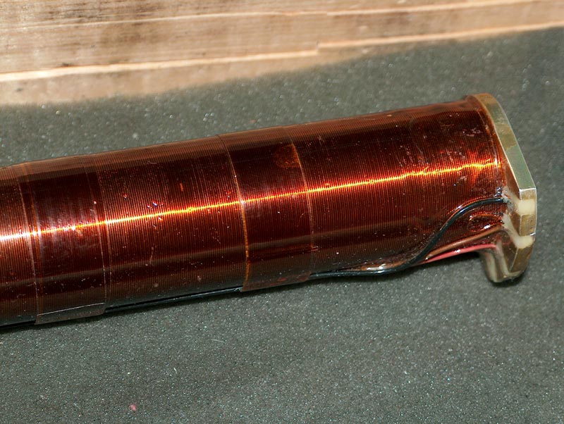
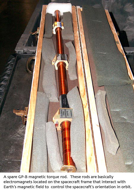
Torque rods are essentially electromagnets, mounted on the spacecraft's frame, that interact with the Earth's magnetic field to place a controlled force, or torque, on the spacecraft, thus changing its orientation. The torque rods on the GP-B spacecraft were manufactured by Ithaco, a division of Goodrich. Each of these rods is 91 cm (35.8 in) long and 3 cm (1.2 in) in diameter. Each rod is made of iron and wound with thin copper wire to form an electromagnet. For redundancy, each rod is actually wound with two long strands of wire, and each coil is powered separately.
Three torque rods are mounted on the base of the spacecraft's frame, each in a position corresponding to one of the spacecraft's three axes, X, Y, or Z. Thus, the orientation of each rod is orthogonal to that of the other two. When current is passed through the coil of a torque rod, the rod becomes an electromagnet, and the strength of the magnetic field generated is a function of the amount of current flowing through the coil. Also, the direction of the current flow determines whether the torque rod generates a repelling or attractive force with respect to the Earth's magnetic field.
Because of their orthogonal positioning, the three rods generate controlled torques along all three axes, enabling the Attitude & Translation Control System (ATC) to control the spacecraft's pitch, yaw, and roll. A torque exerted on the spacecraft by any of the rods reaches a maximum when the rod is oriented orthogonal to the Earth's magnetic field lines and decreases to zero when the rod is directly aligned with Earth's magnetic field. Thus, whenever two of the rods are oriented orthogonal to Earth's magnetic field lines, the third rod will generate no torque.
While orbiting the Earth, the spacecraft's orientation relative to the Earth's magnetic field lines constantly changes, and during most of each orbit, the torques exerted by all three rods are somewhere in between their maximum and minimum values. The ATC can sense the position of Earth's magnetic field at any spacecraft orbital location using magnetometers on-board. In addition, the on-board computer contains a map of Earth's magnetic field, which can be used as a means of modeling it at any given orbital location. The ATC also determines the spacecraft's position and orientation in space using star trackers and navigational gyroscopes, and it uses this data, along with the position of the Earth's magnetic field, to continually compute the amount of current that must be applied to each torque rod in order to maintain the desired pointing direction towards IM Pegasi.
As indicated above, the pointing control afforded by the magnetic torque rods varies with the orientation of the spacecraft relative to Earth's magnetic field, and for this reason the rods alone could not provide the pointing precision required to keep the spacecraft and telescope centered exactly on IM Pegasi. Thus, the ATC system was designed to use the micro-thrusters as the primary means of maintaining the spacecraft's orientation, because their ability to control the spacecraft's orientation is in no way dependent on the spacecraft's orbital position. However, during the science experiment, the magnetic torque rods were used to augment the output of the micro-thrusters, thus reducing the amount of helium required by the thruster system.
At its best during the science phase of the experiment, the ATC was able to achieve a pointing accuracy of ~200 milli-arcseconds (0.000056 degrees). Now, with the thrusters inactive, the magnetic torque rods alone are achieving an average (RMS) pointing accuracy of ~0.4 degrees in the X and Y axes and ~6.7 degrees in the Z-Axis. This is not sufficient precision to keep the spacecraft locked on IM Pegasi, but at times when the torque rod-controlled pointing accuracy is at its best, IM Pegasi does come into the telescope's field of view, and its light registers on the telescope detectors for brief periods of time.
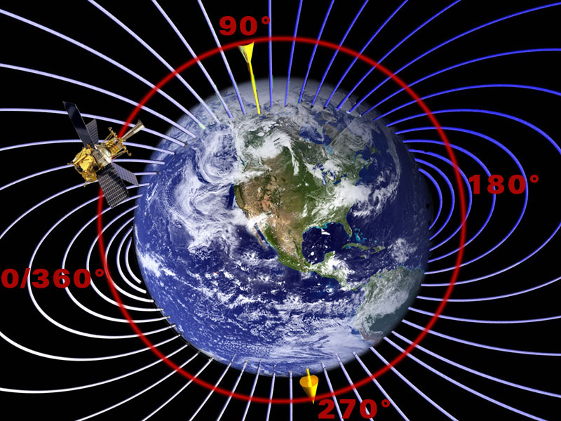
The diagram to the right shows the Earth and its magnetic field lines, with the spacecraft in a circular orbit over the poles. To provide a reference orientation, the spacecraft's position at approximately 9 o'clock, where it is ascending past the equator is labeled 0° or 360°. Likewise, the North Pole is labeled 90°, the equitorial descending node is 180°, and the South Pole is 270°.
 The chart to the right, created last week by our ATC team, is based on the angular positional orientation described above. The two plots in the chart respectively show the magnitude of the average pitch-yaw (X-Y) and roll phase (Z-Axis) pointing error over a period of 45 orbits (3 days) as a function of the spacecraft's position within the Earth's magnetic field. The pitch-yaw and roll phase plots are very nearly mirror images of each other, indicating that when the pitch-yaw pointing is best (lowest attitude error), the roll phase pointing is worst (greatest attitude error) and vice versa. The green vertical lines mark the two best pointing positions in each orbit, and the orange vertical lines mark the two worst pointing positions in each orbit. From these lines, you can see that the pitch-yaw pointing is best at ~60° (11 o'clock) and ~220° (4:30 o'clock) and worst at ~130° (1:30 o'clock) and ~310° (7:30 o'clock).The roll phase pointing is nearly the opposite. It is best at ~120° (1:00 o'clock) and ~305° (7:00 o'clock) and worst at ~0° (9:00 o'clock) and 180° (3:00 o'clock).
Note that the average roll phase error is an order of magnitude greater than the pitch-yaw error, as indicated by the different scales on the two plots. Note also that during the science phase of the mission, when the ATC was using micro-thrusters plus the magnetic torque rods to control the pointing, both the pitch-yaw and roll phase pointing error were consistently below the dotted red line at 0.02° (60 arcseconds), which marks the field of view of the telescope. In fact, as noted above, the average pointing error under micro-thruster control was only about 3/1000 the size of the telescope's field of view.
NEXT SCHEDULED GP-B STATUS UPDATE & MISSION NEWS ON 30 NOVEMBER
Our next regularly scheduled update will be at the end of November. Of course, we will send out a timely update if there are any important changes in the spacecraft's status, or if noteworthy events occur here at GP-B in the meantime.
UPDATED NASA/GP-B FACT SHEET AVAILABLE FOR DOWNLOADING
We recently updated our NASA Factsheet on the GP-B mission and experiment. You'll now find this 6-page document (Adobe Acrobat PDF format) listed as the last navigation link under "What is GP-B" in the upper left corner of this Web page. You can also click here to download a copy.
Drawings & Photos: The composite illustration of a model of the GP-B spacecraft orbiting in Earth's twisting gravity well was created by James Overduin, Pancho & Evelyn Eekels, and Kate Stephenson. The photos of the telescope detectors and magnetic torque rods are from the GP-B photo & graphics archive here at Stanford. The composite drawing of the spacecraft in Earth's magnetic field and the pointing accuracy chart was prepared by GP-B Public Affairs Coordinator, Bob Kahn, with help from the GP-B ATC team. Click on the thumbnails to view these images at full size.
MORE LINKS ON RECENT TOPICS
- Track the satellite in the sky
- Photo, video & and news links
- Build a paper model of the GP-B Spacecraft
- Following the mission online
- Our mailing list—receive the weekly highlights via email
- The GP-B Launch Companion in Adobe Acrobat PDF format. Please note: this file is 1.6 MB, so it may take awhile to download if you have a slow Internet connection.
Previous Update
Index of Updates