WEEKLY HIGHLIGHTS FOR 27 AUGUST 2004:
GRAVITY PROBE B MISSION UPDATE
On Day #129, we have arrived at the second major milestone of the mission—the completion of the Initialization and Orbit Checkout (IOC) Phase and transition into the Science Phase. The spacecraft continues to be in excellent health, with all subsystems performing well. The telescope is properly tracking the guide star, IM Pegasi, during the portion of each orbit when the guide star is visible. Fine precision spin-axis alignment has been completed on gyros #1, #2, and #3, and after the suspension voltages on these gyros were reduced from 10 volts to 200 millivolts in preparation for data collection, a final electrostatic discharge was performed on the gyro rotors using ultraviolet light. Gyro #4 is further behind its fellow gyros and will continue undergoing spin axis alignment awhile longer. Today, the spacecraft was placed in a drag-free mode around gyro #3, and it will remain in this mode for the duration of the Science Phase of the mission, which has now officially begun.
- Over the course of this past week, we completed a number of final adjustments
to the spacecraft and the gyros, in preparation for the transition to the
Science phase. For example, on Wednesday, August 25th, we increased the spacecraft’s
roll rate very slightly from 0.75 rpm to 0.7742 rpm. This moved the signal
frequencies from the gyros out of the range of telemetry sample rate harmonics,
thus improving the signal to noise ratio of the experimental data.
- Throughout most of this past week, we continued fine precision alignment of the gyro spin axes to the telescope axis. Conceptually, this is a straightforward process. Our SQUID magnetometers, in conjunction with the Gyro Suspension System (GSS), can detect very slight imperfections in the gyro rotors, and they utilize these imbalances, enhanced by a suspension force of 10 volts (50 times higher than the science suspension voltage of 200 millivolts) to torque the rotors ever so slightly, causing their spin axes to spiral in towards the target alignment position. However, our success in creating gyro rotors that are almost perfect spheres actually hinders this process. The smaller the level of imperfections in the rotors, the longer it takes the GSS to complete the alignment.
- Today, we completed the final preparations, prior to beginning data collection.
First, we reduced the suspension voltages on gyros #1, #2, and #3 from the
10 volt level used for spin axis alignment to 200 millivolts (0.2 volts),
which is the level that will be used for data collection throughout the
Science Phase of the mission. We use higher voltage in the GSS whenever
we are controlling the position of the gyro rotors. However, during the
data collection phase, we use the lowest voltage required to maintain proper
suspension, so that only the effects of relativity will be influencing the
spin axis deflections of the gyros.
- After lowering the suspension voltages, we used ultraviolet light, shining
through fiber optic cables as we have done previously, to remove any excess
electrical charge that has built up on the rotors. When ultraviolet light shines
on certain metals, it liberates electrons. Two fiber optic cables are embedded
in each gyro housing—one at each end—and each fiber optic cable
terminates at an electrode, located just above the rotor surface, When the
ultraviolet lamps are turned on, electrons form between the electrode and the
rotor surface, and by changing the bias on these electrodes, we can control
the direction of electron flow, either towards or away from the surfaces of
the rotors.
- Finally, this morning, we commanded the spacecraft into back-up drag-free mode, balanced around gyro #3. After testing the spacecraft in both primary and back-up drag-free modes over the past few weeks, we have determined that back-up drag free mode has yielded the most reliable and efficient performance, and thus, the spacecraft will remain in this mode for the duration of the Science Phase. We will continue tuning the drag-free performance of the Attitude and Translation Control (ATC) system in the early portion of the Science Phase to correct for a previously reported, unknown force, which is causing excess helium flow from the Dewar through the micro thrusters. The current science configuration of the spacecraft has very little margin for increased helium flow.

In next week’s highlights, we will look back over the IOC period and put it into the perspective of the whole mission. In the process of doing this, we will hopefully answer a number of email inquiries we have received recently regarding the health, longevity, and success of the GP-B mission.
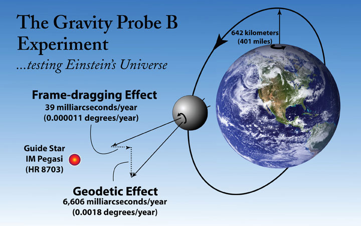
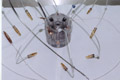
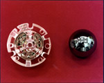
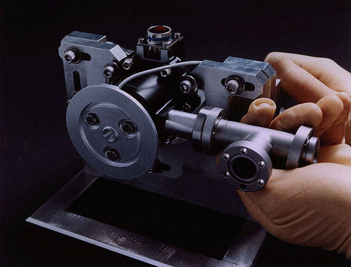
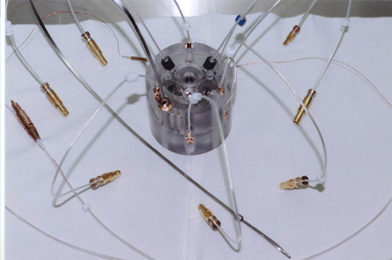
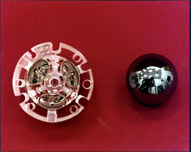
Photos & Drawings: The diagram at the top of the screen depicts the GP-B experiment. All of the photos are all taken from the GP-B Photo Archive here at Stanford University. They show a micro thruster, the image divider assembly at the top of the science telescope, an assembled gyro housing, including the fiber optic cables that shine ultraviolet light on the gyro rotors (spheres), and one half of a gyroscope housing with a gyro rotor. Click on the thumbnails to view enlarged copies of these images.
Please Note: We will continue updating these highlights and sending out the GP-B email update on a weekly basis through the first few weeks of the Science Phase of the mission. Then, as mission operations become routine, we will reduce the frequency these updates to biweekly. However, from time to time, we intend to post special reports and special updates, as warranted by mission events.
SWISS AMATEUR ASTRONOMER PHOTOGRAPHS GP-B GP-B SPACECRAFT IN ORBIT WITH GUIDE STAR IM PEGASI
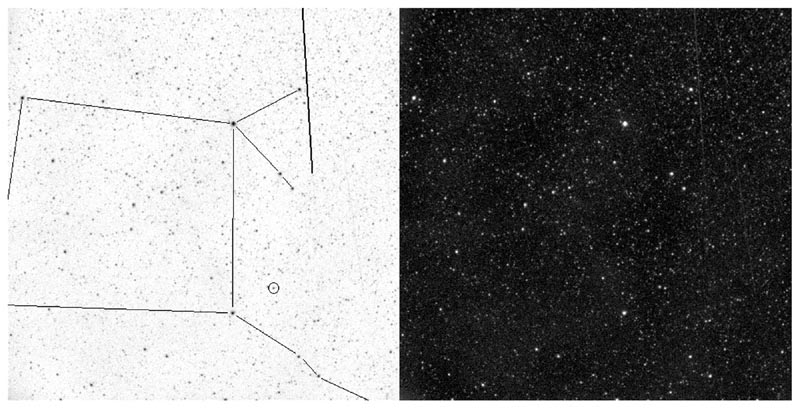
To the right, is a thumbnail of a photograph of the GP-B spacecraft in orbit, along with the guide star, IM Pegasi. (Click on the thumbnail to view the photo at full size.) The photo was taken and emailed to us by Stefano Sposetti, a Swiss physics teacher and amateur astronomer. Stefano used a 40cm newtonian telescope, with a CCD camera and 20mm wide field lens attached to make this photo. He then sent us the two versions shown — the normal (black sky) version on the right, and an inverse version in which the constellation, Pegasus, the guide star IM Pegasi, and the path of the GP-B spacecraft are highlighted for easy identification on the left.
We are grateful to Stefano for sending us this wonderful photo. You can view other astronomical photos that he has taken on his Web page: http://aida.astronomie.info/sposetti. Following is Stefano's description of his photo:
In this picture one can see the quite dim GP-B satellite traveling from North (up) to South (down) direction. The bold line in the right part of the left image represents the satellite trail just before entering the earth shadow. (Every satellite becomes visible because it reflects the sunlight). The connecting lines show the constellation Pegasus. The small circle around the star is IM Pegasi, the guide star used by the spacecraft's telescope in his experiment! GP-B is a circumpolar satellite following a free fall trajectory about 640km above the earth surface. From my location the satellite passed that night at a maximum elevation of 87degrees, thus not exactly overhead. The brightness of the satellite was between 3mag and 4mag. The Moon, about in the last quarter phase, illuminated the sky and was a drawback for having a good signal/noise ratio of the satellite trace. I took this 60-seconds black and white CCD picture with a 20mm,f/2.8 lens on august 6 centered at 01:19:00 UT. North is up, East is left.
More links on recent topics
- Track the satellite in the sky
- Photo, video & and news links
- Build a paper model of the GP-B Spacecraft
- Following the mission online
- Our mailing list - receive the weekly highlights via email
- The GP-B Launch Companion in Adobe Acrobat PDF format. Please note: this file is 1.6 MB, so it may take awhile to download if you have a slow Internet connection.
Previous Highlight
Index of Highlights