 1 |
 2 |
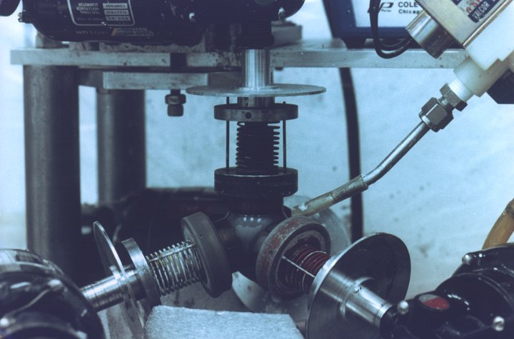
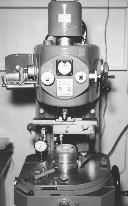
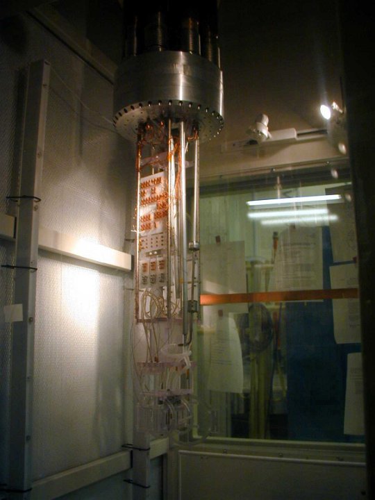
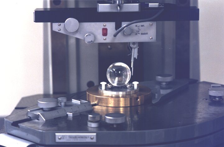 3 Quartz rotor mounted in the Talyrond machine for roundness measurement. September, 1989 |
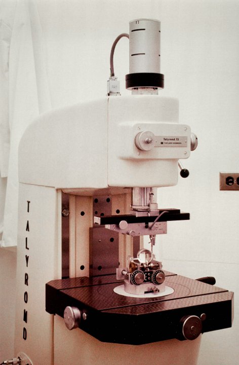 4 View of the Talyrond machine, used to check the roundness of the finished rotors. |
 5 Close-up of a rotor being polished on the lapping machine. April, 1991 |
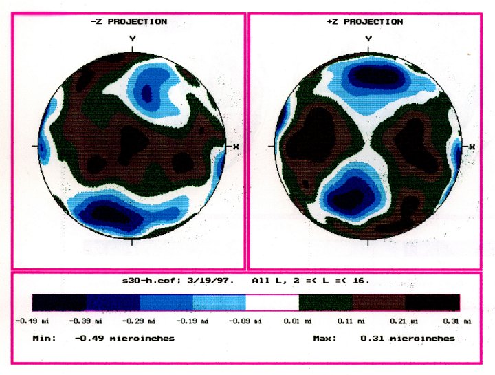 6 Diagram showing the surface variations on a completed gyroscope rotor. |
 7 Image of a rotor being measured on the Talyrond machine. Professional image taken for Popular Science. Copyright owned by Michael Freeman |
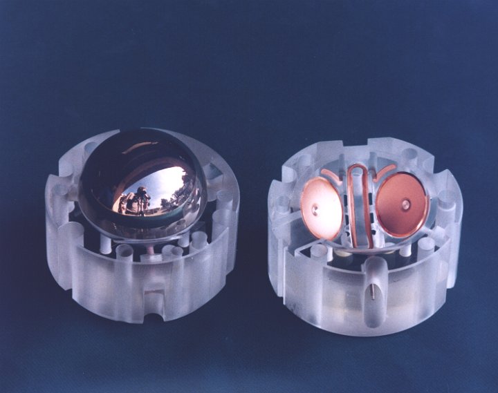
 8 Non-flight gyroscope housing with a SQUID readout line installed. |
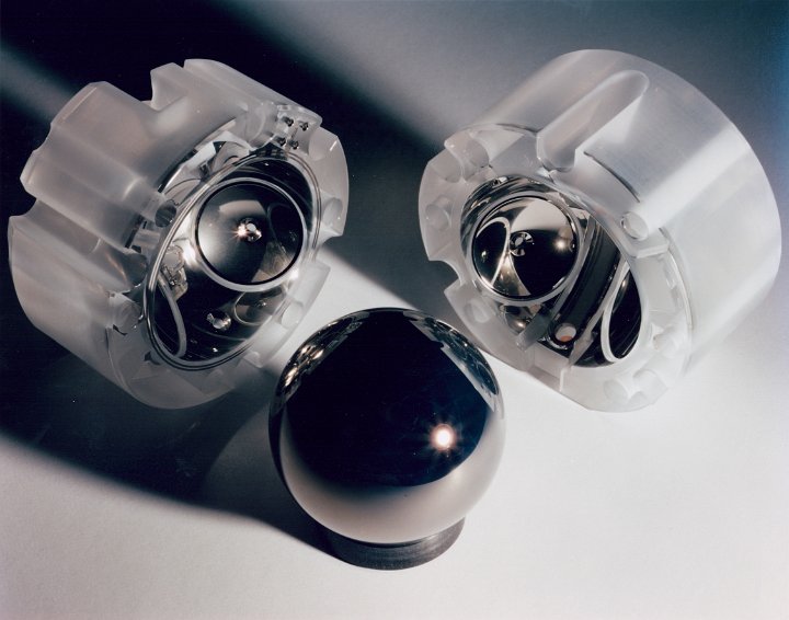
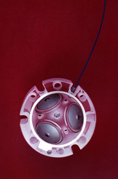
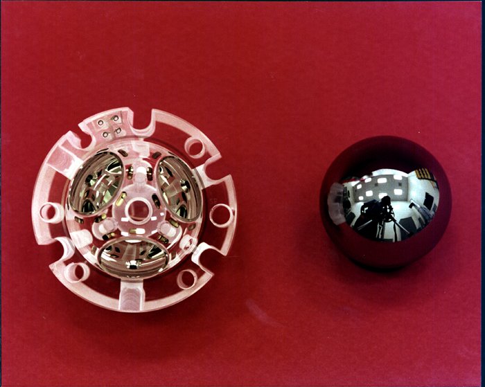
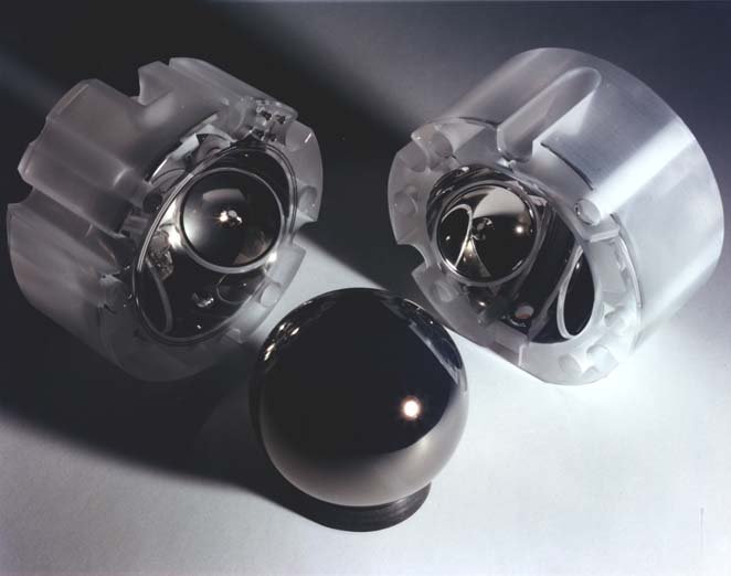
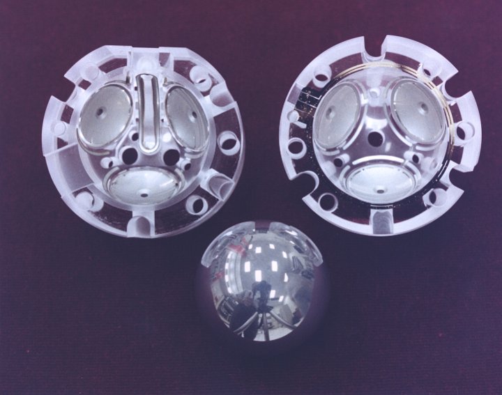 9 Non-flight coated rotor and two housing halves on a red background. |
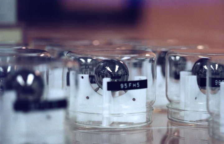
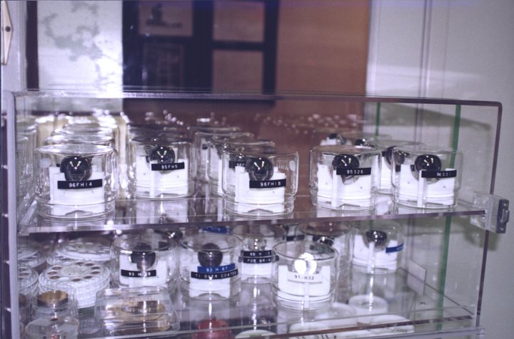 10 Clean cabinet full of completed and flight qualified rotors. |
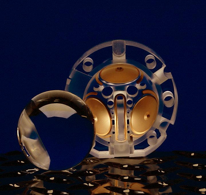
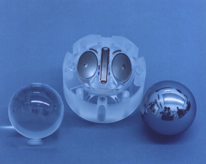 11 A coated and uncoated quartz rotor sit next to half a housing on a light blue background. |
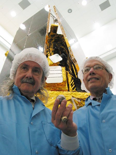 12 Everitt-Parkinson-gyro-rotor GP-B PI Francis Everitt and Co-PI Brad Parkinson show a gyroscope rotor in front of the spacecraft. |
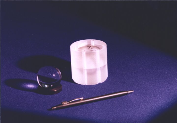 13 A dummy quartz housing and an uncoated quartz rotor sit next to a ball point pen for scale. |
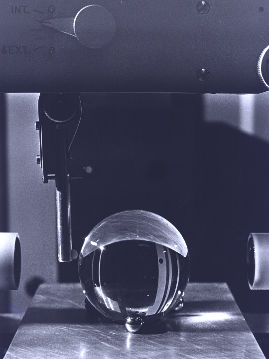
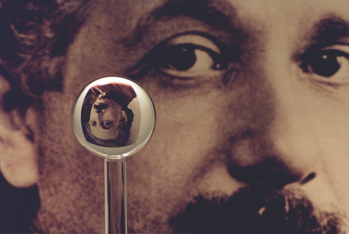 14 Close up of a clear, uncoated quartz rotor. A poster of einstein is shrunk and flipped in the clear material. |
 15 Talyrond machine at MSFC (Marshall Space Flight Center). A quartz housing is shown mounted for measurement. October 13th, 1979 |
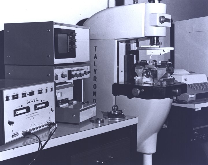 16 Talyrond machine and supporting equipment at MSFC (Marshall Space Flight Center). October 13th, 1979 |
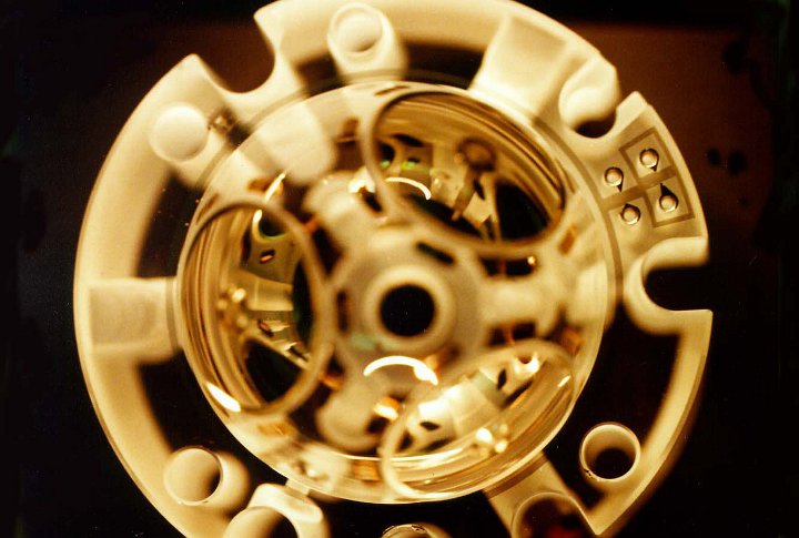
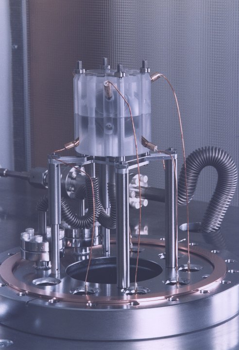
 17 View of the commissioning mechanism used to test the flight gyroscopes. |
 18 The safely removed gyroscope 4, complete with housings, spin-up lines and readout cables. |
 19 Close-up of a back-lit gyroscope housing. |
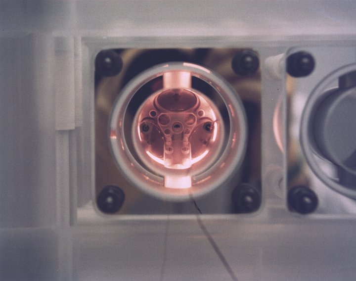 20 Looking down the housing bore into a back-lit gyroscope. This was taken while the gyroscopes were being inserted into the quartz block. |
 21 Close-up shot of a single silicon crystal rotor. |
 22 |
 23 View of the coating mechanine used to to cover the gyroscope rotor with a very thin layer of superconducting material. |
 24 |
 25 The number four gyro is inspected under monochromatic light after it was removed from the SIA ( Science Instrument assembly). Aug. 2000. |
 26 close-up of rotors in the clean cabinet |
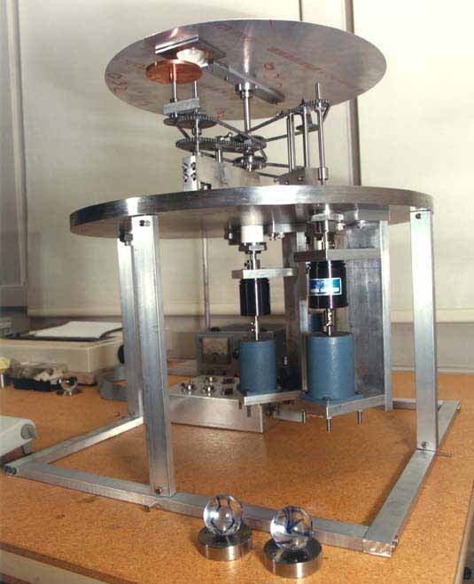
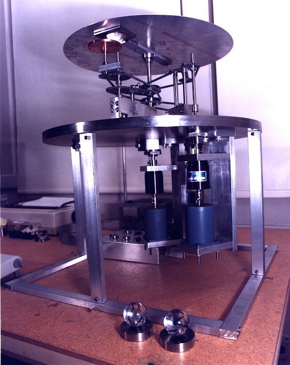 27 This is the new ball walker assembly. The various sprockets and gears automatically position the quartz rotor, which can be seen in the aluminum disk. The disk is positioned underneath the sputtering head to ensure uniform coating of the rotor with niobium. This thin layer of niobium forms the superconducting surface of the gyroscope rotor. |
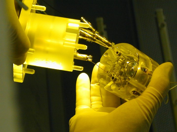
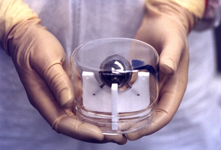 28 View of a pair of gloved hands holding an encased flight gyroscope rotor |
 29 |
 30 Gyroscope in FIST orientation, installed in room temperature test system. 1989 |
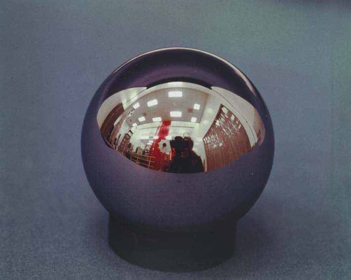
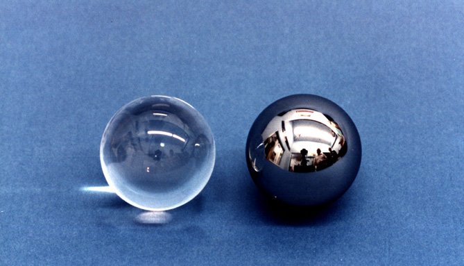 31 Image of a coated and an uncoated quartz rotor. The rotors are covered in a thing layer of niobium metal, which allows them to levitate when they are in a supercooled environment. |
 32 Coated quartz rotor and two housing halves on a green background |
 33 View of a backlit uncoated quartz rotor and half a housing on a purple background. |
 34 Close-up of a coated rotor in a gloved hand. |

