The GP-B Probe Thermal Rework
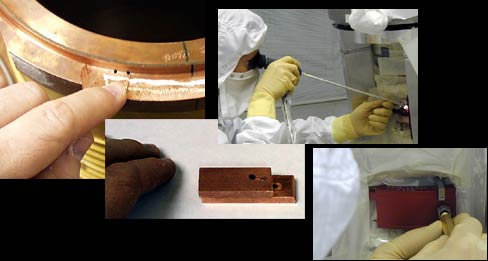 The probe rework began with the idea of drilling small holes and placing pins
into the four Heat Exchangers on the probe neck of Gravity Probe
B. Looking at the photo collage from the top left to the right, the first picture
is of a non-flight probe with the proposed holes drilled, and
below this appears a picture of the prototype pinning mechanism.
The pin is actually in the smallest middle hole.
The probe rework began with the idea of drilling small holes and placing pins
into the four Heat Exchangers on the probe neck of Gravity Probe
B. Looking at the photo collage from the top left to the right, the first picture
is of a non-flight probe with the proposed holes drilled, and
below this appears a picture of the prototype pinning mechanism.
The pin is actually in the smallest middle hole.
To drill the probe requires that we remove much of the exterior
sensitive equipment, such as our vatterfly valves, because some
of it was in the way, and because some parts required further inspection. Additionally, the
probe contains a series of four optical windows designed to allow the passage of the optical
image of the guide star but to reduce the heat transfer at infrared wavelengths.
We had to remove these telescope windows from inside the probe in order to measure the
positions of the internal heat stations relative to the external ones, and to
clean them. Cleanliness and integrity of these windows is critical to the
success of the mission.
The procedure in drilling the HEX (Heat EXchanger) pin holes was to
remove a window and do the necessary drilling and pin installation while
leaving remaining windows in place. The remaining windows deeper in the
body of the probe and closer to the telescope itself would protect
against debris actually falling into the telescope should there be a drilling
error and the probe neck penetrated.
The telescope windows feature a unique design: they may only be
installed in the proper orientation and order. They cannot be accidentally
interchanged or incorrectly installed. One of the windows can be
seen in the lower photo collage, in the lower left hand corner. The replacement
of a window into the probe is shown in the top right corner of the lower collage.
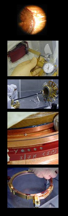 The drilling itself utilized a sturdy red metal drill guide on the probe neck
referred to as "tooling". A boroscope was used before and after changing
each drill bit to inspect the smoothness of the hole, ensure that all debris has been removed
and detect the staightness & positioning for Quality Control. The top left corner of the
lower photo collage shows the view through the boroscope looking down in detail at the hole.
Different drill bits were used during the drilling, ending with a brittle but hard titanium bit.
Every time the drill was used the hole was checked for cleanliness. It could have contained shavings
or drill bit debris. The empty bores were cleaned with alcohol which served
dual purpose as a lubricant during the drilling.
The drilling itself utilized a sturdy red metal drill guide on the probe neck
referred to as "tooling". A boroscope was used before and after changing
each drill bit to inspect the smoothness of the hole, ensure that all debris has been removed
and detect the staightness & positioning for Quality Control. The top left corner of the
lower photo collage shows the view through the boroscope looking down in detail at the hole.
Different drill bits were used during the drilling, ending with a brittle but hard titanium bit.
Every time the drill was used the hole was checked for cleanliness. It could have contained shavings
or drill bit debris. The empty bores were cleaned with alcohol which served
dual purpose as a lubricant during the drilling.
After drilling of a hole was complete, the hole was left with a pointed end,
because the drill bit is a pointed instrument. This point had to be reamed out with a
special tool so that the pins would fit exactly and cylindrically. After reaming, the pin
itself was inserted, shown here in the top photo grouping, lower right hand corner.
Pins were put in to each Heat Exchanger location at 51 degree angles and also straight
on at zero degrees. The copper pins are hollow so that any air would not be trapped
beneath the pins during their insertion. Trapped air could cause a virtual leak.
After insertion, the hollow centers of the pins were backfilled with a special,
low-viscosity epoxy. After the zero degree pins were inserted & epoxied,
a copper slug of larger diameter (called a "doubler") was inserted along with
proven vacuum-tight epoxy known in industry as "Blue Death".
For the 51 degree hole pins, due to orientation, a slug was not
needed and a thin copper sheet, specially grooved to fit the probe rim,
was epoxied on, again using Blue Death. The doublers were needed to seal the pins into place
and keep out virtual leaks (the fit is very tight). The bottom right hand corner of the lower
photo collage shows a 51 degree angle pin before its doubler was installed. It's the very
small hollow pin in the rim of the copper, just up and left from the center
(not in the red drill tooling mechanism).
After insertion, the depth of the pin in the Heat Exchanger was measured.
We had to make sure the fit was perfect. In the lower photo grouping, the lower middle
picture shows a gauge with a set of calipers to measure the actual depth of the pin
insertion instrument, implying the depth of the pin in the probe.
Great accuracy in work was specified to prevent drill-though into the probe's inner volume - a problem which could have introduced
contaminants directly into the probe and made vacuum sealing potentially more difficult. The painstaking and
challenging work was done at a higher accuracy even than that specified,
and its completion marks a major NASA milestone for our team.