The GP-B flight gyroscope is a sphere of fused quartz, 1.5 inches (38 mm) in diameter. It is electrically suspended by applying voltages to the saucer-shaped electrodes seen in the two halves of the housing. It is spun up to 170 Hz by gas running through the circumferential channel visible in the right-hand hemisphere, after which the gas is pumped out and the ball runs freely in a vacuum. The direction is read out by a SQUID connected to the superconducting circuit on the face of the left-hand hemisphere.
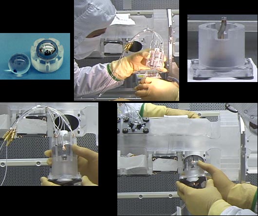
- Two prototype gyroscope rotors, one before niobium coating was applied and one after the coating, and one half of a gyroscope housing.
- Engineer Chris Gray holding a rotor encased in its two housing halves, with readout cables attached. Dr. Doron Bardas, whose hand is in the lower right corner, is holding the other portion of the assembly.
- The other portion of the flight gyroscope assembly (with gas exhaust valve at the top).
- The full flight gyroscope assembly, with readout cables attached.
- The assembly being inserted into the quartz block by Dr. Doron Bardas.