In late 1999, it was determined that the connection between the housing of Gyroscope #4 and its SQUID readout cable was not superconducting. A non-superconducting connection is a non-functioning connection for a Gravity Probe B gyro. While the mission can accomplish its science objectives with only three gyroscopes, we would experience a degradation of experiment error from 0.15 marcsec/yr to 0.17 marcsec/yr. We would also find ourselves in the potentially risky position of reduced redundancy should anything go wrong with our three remaining gyros in flight. After verifying that the cause of the initial gyro problem was correctly diagnosed, we decided to remove and replace Gyro #4 while the probe was out of the dewar for the thermal payload recycle (please see the highlight for June 2, 2000 for more details). A new cable design was already in place for flight gyros 1, 2 & 3, so they were not facing a similar problem. The gyroscopes, their housings and their connections are in highly sensitive locations for contamination and breakage; removal and reinsertion were tricky operations. The replacement operation was practiced over and over with prototype parts to minimize the risks to Gravity Probe B.
Removal of a Gyro
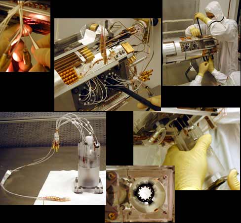
The technicians, Chris Gray, Ken Bower and Bruce Clarke, first cut the tie downs on the spinup and exhaust lines, cleaned with alcohol prior to disconnecting LEMO connectors, and all electronic suspension lines. The top center picture shows the orange striped capton sleevings and the LEMO connectors underneath it on the left. The epoxy is then broken to eventually remove the screws that hold down the caging retainer (which holds the caging assembly into the gyro). The staking on the caging retainer assembly is removed and the UV Bias lines are disconnected using tweezers (as shown in the upper left-hand photo). The suspension lines and UV cables are tied up in preparation for gyro removal; shown in the top center picture, the lines are bundled up on the right side of the photo, out of the way. The caging assembly is unscrewed and bagged for cleanliness, but is still connected to the probe, again out of the way. See the small caging assembly bagged and taped in the top center photo, at the top. It is essential to prevent any contamination to the gyro, so even though the guys are working in a class 10 clean room (that's no more than ten particles per cubic inch in the air!), they need to install a plug into the caging hole of the gyro to seal it against any contaminants. The white plug is shown in the lower left photo at the top center of the gyro assembly.
After cleaning and lubricating the plastic suspension line lower grommets (those little white disks lined up in a circle in the top center picture), Chris pushes the grommets out of the retainer so that gyro removal is possible. The retention rod removal tools are put in place and finger-tightened so that we can remove snap rings and washers. Ken Bower and Chris Gray then co-ordinate the tension of the retention rods and their removal tools, as shown in the top right-hand photo. Equal pressure on all 4 rods are essential to a successful operation. The rods are in Chris' hands at the bottom of the photo. This delicate evening-out of pressure required several iterations. Finally, Ken Bower pushes the gyro from its probe bore towards Chris after the removal of the snap rings and washers. The bottom right photo shows Chris carefully easing the gyro out of its bore. The black rod Ken is using is just barely visible at the top of the gyro assembly.
All the while that the gyro is on its way out of the probe, Bruce Clarke stands ready with tweezers to catch the index-plate-spacer-to-quartz-block dowel pins. There are 4 quartz dowel pins which must not be dropped as the gyro is removed. These fragile quartz pins will be needed in perfect condition later for the re-insertion of the gyro assembly. You can see Bruce in position in the small photo on the main highlights page.
Finally, success: the full gyro #4 assembly with UV and suspension lines attached is shown at the bottom left. In the bottom center photo is Quartz Block Bore #4 with the Gyro retainer and the local magnetic shield (the metal sleeve inside the bore) still in place.
Insertion of a Gyro
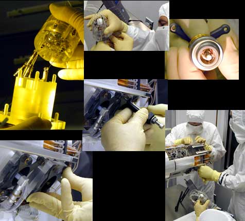
After inspecting the bore and the gyro assembly for contamination and any cracks with a green, monochromatic light, and removing any contamination, the team is ready to assemble the new gyro and start the insertion process. The top center photo shows Chris Gray checking the readout loop of the new housing assembly. While under the monochromatic light, the entire gyro assembly is checked for contamination and material faults in the top left photo. You can see the UV Bias lines stretching from the housing assembly to the index plate, and the delicate quartz dowel pins used to fit the gyro assembly together in this monochromatic photo. To avoid contamination, Chris must do his work on the gyro assembly without ever touching the top of the spacer plate. In the top right photo, the caging assembly is thoroughly checked for contaminants and any damage. The center photo shows the retaining rods being returned, while the balancing act for proper retaining rod pressure is performed yet again. In the lower right hand photo, Ken, Chris and Bruce prepare to integrate the new assembly into the quartz block. Bruce is holding the assembly in the lower part of the picture. The bottom left hand photo shows the assembly during its final insertion. The entire insertion was performed within necessary tolerances and exacting cleanliness standards. GP-B extends its congratulations to the team, whose members include Ken Bower, Rob Brumley, Bruce Clarke, Chris Gray, David Hipkins, and Russ Leese.