Simple questions don’t necessarily have simple answers, at least if you want to get them right. Sometimes an innocent-sounding question can require a whole thesis or more to answer correctly. The answers here are a mix, a compromise between a fully detailed response and none, but they try to get the important ideas across; if for no other reason than to show that we know what we are doing. If you have a simple question that’s not in this list, let us know.
Why would the test masses fall when they are in orbit at constant height?
The test masses are always falling, in orbit. That’s why weightlessness is sometimes called free fall. It is important not to confuse falling with changing height. Like a projectile, a satellite is always falling, but it is moving sideways at the same time, so after it’s gone (for example) a kilometer horizontally, it’s fallen eight centimeters or so below perfectly straight travel. But the Earth is round, and its surface curves downwards eight centimeters in the same distance. So the satellite will be the same height above the Earth as when it started. Same thing in the next kilometer, and the next...until the satellite gets all the way around, at the same height it started at. But it’s fallen all the way, it just happened to miss hitting the ground. See also, The Hitchhiker’s Guide to the Galaxy. The same is true of the test masses inside the satellite. They are falling too, nothing is holding them up. The satellite is there mostly to protect them from the wind of their motion, which although very thin at that altitude, would still seriously disturb our experiment. To keep the satellite itself from being disturbed or slowed by this air drag, we fire little jets—the helium thrusters—which exactly cancel the drag, as long as the helium lasts.
How do you pick test mass materials?
An interesting issue. How do you select materials to maximize their response to an unknown effect? There are three issues here. To maximize information return about the violation (whether any particular class of material falls faster, for example), you want to pick as many different materials as possible. The differences must be significant—it won’t do to select all similar materials. Second, to maximize certainty about the result—whether or not there is a violation—you should repeat the same experiment many times, changing at most one thing at a time, and have a few checks like the cyclic condition (below). If nothing you do changes the result, it may be real. Third, to be able to do the experiment at all, you have to pick materials that can be manufactured in the shapes and tolerances needed. There’s an additional constraint, NASA isn’t going to let you fly as many materials as you’d like—it’s expensive. Only a few pairs of materials will be allowed. The baseline mass choice, niobium, platinum-iridium, and beryllium, reflects a complex trade between these issues which emphasizes certainty in the result and manufacturablity over information return. The masses are arranged in a “cyclic condition” with one pair of masses (Pt-Ir/Be) duplicated in another accelerometer. The platinum-iridium masses are always in the center, and the beryllium masses are always outside. This prevents having a mass difference so large that it cannot be compensated by adjustments to the sensor coils. The final materials choice was based first on a selection of manufacturable materials, and then on the requirement that the materials be different in properties that might contribute to an Equivalence Principle violation, such as proton/neutron ratio, nuclear binding energy, and the like.
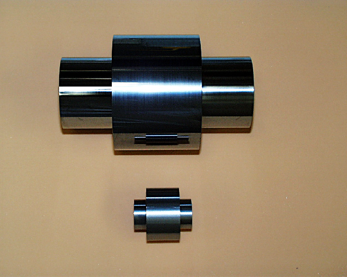
Beryllium & Niobium Test Masses
What is a "cyclic condition"?
This is the name given to a type of test for systematic errors. As applied to STEP, suppose we have three materials A, B, and C. The differences in acceleration A-B, B-C, and C-A between masses A and B, B and C, C and A, will add to zero if there are no systematic disturbances. If the sum (A-B)+(B-C)+(C-A) is non-zero, there is certainly a systematic disturbance. This powerful and model-independent technique for detecting systematic errors has been implemented in the arrangement of STEP test masses.
What is the reason for the shape of the masses?
It is well known that spherical objects respond to gravity like a point particle. It's less well appreciated that non-spherical objects don't usually do so when the gravity field is non-uniform and varies from one place to another. In a uniform gravity field the shape doesn't matter.
Consider a yardstick in the earth's gravity. The earth's gravity weakens with height, so if the yardstick is held vertically, one end is closer to the earth, and feels slightly stronger gravity. The high end likewise feels a little less gravity. There's a little excess which means that the yardstick falls a bit faster than a point particle at the yardstick's center of mass. Some people say the yardstick's center of gravity is below its center of mass. For a similar reason (can you find it?) a thin disklike a pancake falls a bit more slowly than a point mass.
STEP's test masses are cylinders, so we can put one inside the other and be able to get to it for measurements and things. There's an optimum shape for a right circular cylinder, between a yardstick and a pancake, which has its principal moments of inertia all equal. This shape solves the problem if the gravity gradient (the change in gravity with height) is uniform, and makes the cylinder fall at the same rate as a sphere. But what if the gravity gradient is not uniform? Then there's a little more complicated shape, which still has its moments of inertia all equal, but has a belt around the middle. Actually there's a whole bunch of such shapes. And what if still higher derivatives are not uniform? You can continue as far as you like, making the non-spherical mass act as much like a sphere as you want, adding extra little belts and ridges until you get tired of it. We stopped with the belted shape, because the accuracy of manufacture becomes an issue, and because it's good enough for the sensitivity we want. Note that the gravity gradients that disturb us the most come from masses in the satellite, not from the earth as in the example. Because masses in the satellite (radios, batteries, liquid helium,...) are much closer than the Earth, their gravity gradients are as strong as those coming from the Earth. The higher-order gradients, in particular, decrease very rapidly with distance, and are a much larger concern coming from the satellite than from the Earth.
What about disturbances from higher moments of the Earth?
The biggest coupling to the differential mode is from the first order gravity gradient of the Earth. That has magnitude A" (3/2)gDx/r where g is the gravity at orbit height, r is the orbit height, and Dx is the distance between the centers of mass. The next higher moment is proportional to g(da/r)2, where a is the uncertainty in manufacture of either mass. That's a good deal smaller than A by da2/(r Dx ); depending on assumptions about the relative size of Dx and da, maybe several million times smaller (r is about 6.8´106 meters, da is a few microns, Dx less than 10-9 m). But Dx was picked to keep A from saturating the accelerometers, so A is less than about 30,000´10-17 g ; and a million or so times smaller than that is 1/30 of our estimated sensitivity. So these disturbances are not very important, but shouldn't be neglected either.
That's within one accelerometer. For comparisons between accelerometers, the higher moments of the earth are important; that's because separate accelerometers are so much farther apart-15 cm instead of ~10-9 m. In this case the disturbance is caused by small changes in the Earth's gravity gradient from point to point in the orbit, rather than higher gradients coupling directly to the test masses. These changes produce force at right angles to the sensitive direction, and are further reduced by the common mode rejection of the accelerometers, so things aren't quite so bad as the increase in length suggests. The remaining disturbance is probably a few hundred times our sensitivity, and can be further reduced during data analysis by calibration of the common mode rejection and modelling of the disturbance.
You can learn quite a lot about mass distribution in the Earth from measurements between accelerometers, and at one time STEP had a geodesy co-experiment to do just that; but it was cancelled for budgetary reasons. Too bad; the data would have enhanced the Equivalence Principle measurement as well. But we can achieve a good measurement anyway, because the disturbances from these higher Earth moments don't exactly resemble an Equivalence Principle violation. They differ in frequency (always at some harmonic of the orbit) and phase (always at the same place over the Earth), so they can be distinguished from a violation in data analysis.
Why don't you use spherical masses?
This issue has been raised several times in different versions of STEP, and we've had a lot of fun with it. The supposed advantage is that ideal spheres act like point particles, leading to a simplification in the design. For example, we had to go to a lot of effort to design the STEP test masses so they won't interact much with external gravity gradients, and they have to be made very carefully. That might not be needed with spheres, which are a simple design and fairly easy to make.
To keep the gravity gradient between the spheres from being too large, their centers of mass have to be at the same place. This can be done with hollow objects (as well as some really weird shapes), but is a particular problem with spheres. So the first problem is the inner sphere has to be put inside the outer sphere somehow; the best idea is to cut the outer one in two and reassemble it. So the outer sphere at least is no longer ideal, and you have the manufacturing problem of how to make two perfect hemispheres and joining them (much harder than simply making spheres). The next issue that has to be addressed is how to measure the position of the inner sphere. There are several techniques, from x-rays to software estimators (see the question on the usefulness of radiation sensors) that might do the job, and they are all slightly unsatisfactory, including a transparent outer sphere. The spheres have to be accurately centered on each other, and how do you manage that when you can't push on them independently? This suggests that holes are needed in the outer sphere, to push through. But you have to cut holes in the outer sphere anyway, to get any gas out-gas usually causes big disturbances-and to be able to control the charge on the inner sphere. No one has figured out how to degas without a hole, and if the inner sphere is charged you are sure to get some disturbance. If you are going to have holes, you may as well do the measurement job with SQUIDs or some other satisfying scheme. With holes in the outer sphere, especially small ones, you have to control its orientation very carefully to keep them aligned properly, and that's hard with a sphere. Finally, even without holes, you have to keep the spheres from turning at random-because they're not perfect, even if they are perfectly shaped. They will have density variations and their centers of mass will not be at the centers of the sphere, which will lead to measurement errors as the spheres turn around their centers of mass. Not to mention the gravitational couplings that you thought you'd gotten rid of when you selected the spherical geometry. All of this imperfection must be accounted for. Having done all this, the spheres are no longer spheres, they never were, quite; so you have to do a lot of calculations to use them, and come up with some good ideas, and do extremely careful machining to make them; It's not so simple as was believed, and it is looking like a development project in its own right. Which leads to the question, why bother? In the final analysis, and given the same cleverness in solving problems like those above, the performance of both perfect spheres and STEP belted cylinders is limited by density variations in the material, which is about the same in both cases; and the cylinders are much easier to make and work with.
What are STEP's pointing requirements?
STEP has no pointing requirements in the usual sense of the term. Rather, STEP uses the satellite attitude as a control input to reduce gravitational disturbances from the Earth. It does not matter what the attitude is, so long as the disturbances are minimized. We can use whatever attitude does the job. The correct attitude is found by using the gravity gradient disturbance as an error signal. This disturbance is proportional to the angular deviation from the best attitude. Changing the attitude controls the disturbance, so we implement a feedback loop which corrects the attitude until the disturbance is nearly zero. Then the satellite will automatically be pointing correctly. The "correct" attitude which minimizes the disturbances will be a fraction of an arc second from the instantaneous orbit normal, but this should not be confused with a requirement. Because the error signal is internal we wouldn't even need to know the attitude, if we didn't need to know the roll rate and phase of any Equivalence Principle signal. There are requirements on rotation of the satellite. Rotation is used in STEP to modulate the Equivalence Principle signal and distinguish it from fixed-frequency disturbances. For this the satellite must rotate up to three times orbital rate in either direction, and at constant rate during measurements. There is a requirement that the rate be constant to 1% of orbit rate, to keep the signal frequency constant and to prevent variations in centrifugal force which might disturb the measurement.
Why don't you use a torsion balance?
A torsion balance is a complex, rigid object which can't have its center of mass adjusted easily. The STEP test masses are free to move, simply shaped, and we can put their mass centers precisely at the same place, reducing many gravitational disturbances from the Earth and satellite. Moreover, the torsion fiber is redundant in space because of the weightless conditions, and it is as likely to be a source of disturbance as not, at the levels we are aiming for. The shapes and positions of our masses can be controlled much more accurately than a rigid rotor, made of two or more materials, can be made.
How does the mass centering work?
Two objects not at the same position are generally in slightly different gravity fields; the difference in their gravitational acceleration will be A =Ñg·DX, where DX is the difference in position and Ñg is the gravity gradient. The accelerometer measures A, and we work backwards to find an estimate for DX. Then we move the masses to reduce DX. This adjustment is made repetetively under computer control until DX is as small as possible. The limitation is the drag free residual acceleration in the differential mode. When the remaining acceleration from gravity gradient is smaller than the residual, no further adjustment is possible. The magnetic bearings are made in quadrants so we can adjust the masses' positions easily by changing the current trapped in them. After adjustment these supercurrents will be permanently trapped and never change. The stability of the adjustment depends on the stable supercurrents rather than a possibly variable current supply. The centering error signal A occurs at twice the frequency of the Equivalence Principle signal, and can always be distinguished from it.
How does the gravity gradient pointing work?
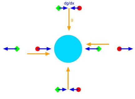
Any two differential accelerometers will measure slightly different common mode accelerations if they are at slightly different heights in the Earth's gravity. The difference in their common-mode gravitational acceleration will be A =Ñg·DH, where DH = L sin q is the difference in height for two accelerometers separated by L, q is the angle L makes wih the horizontal, and Ñg is the gravity gradient. This acceleration is used as an error signal in much the same way as the mass centering; but the controller uses the angle q, i.e. satellite attitude, as a control input to minimize A, rather than the distance between mass centers. Why is the gravity gradient disturbance at twice the signal frequency? It's a matter of geometry. The gravity gradient is symmetric about the horizontal plane, while the total gravity is not. So when the experiment rotates, the gravity gradient changes direction twice per rotation, and the total gravity only once. The illustration shows how the total force and difference in force between two objects change at different positions around the earth. The gravity vector always points toward the earth, and points in opposite directions on opposite sides. It changes sign once for each revolution. The gravity gradient is symmetric about a plane through the midpoint between the masses, and hence looks the same on opposite sides of the earth. It is reversed when the masses are at 90 degrees from their original position: hence, it changes sign twice rather than once. This difference between the gravity gradient force and the total gravity allows us to distinguish between the signal of an Equivalence Principle violation, which depends on total gravity, and disturbances caused by the gravity gradient.
What disturbances are caused by rotating the satellite?
So long as the rotation is smooth, none. In the rotating frame, centrifugal force is constant, and everything in the satellite is at rest so coriolis force is zero. If the rotation rate w is slightly variable, and if the masses are off-center by a distance R which varies an amount dR, the centrifugal force will vary by 2wRdw+w2dR; since the centrifugal force contributes part of the total spring constant restraining the masses, this produces a small disturbance (~10-15 m/sec^2) in the common mode, a small part of which appears in the differential mode. The rotation itself does not cause any disturbances, but it may cause some disturbances to appear at different frequencies and with different amplitudes. Chief among these are the effects of thermal distortion of the spacecraft, eccentricity of the orbit, earth gravity gradient, any helium tides, and so forth.
What disturbances are caused by the masses being off-center in the rotating satellite?
Two of the test masses define the rotation axis, and therefore can never be off-center. The others get moved to the rotation axis during the centering process, so they are also on center. The drag-free system provides all the forces and torques needed to keep the satellite's rotation axis centered on the test masses. The remaining disturbance is just the drag free residual acceleration, which has to be dealt with anyway.
What are the star tracker requirements?
The STEP star tracker needs to be able to measure angles of about 10 arc seconds. The star tracker is only a minor input to the attitude control, so the requirement is driven mostly by the need to have a very steady slow rotation. The star tracker must be able to measure the rotation in a small fraction of a turn.
Why don't we want any moving parts?
If the satellite weighs 500 kg, a part that weighs 5 gm and moves 1 cm will cause the whole satellite to move in response by 1´10-7 m. This is in the common mode of the accelerometers, and about 10-4 of it will appear in the differential mode-as big as our Equivalence Principle sensitivity. Rapid motions cannot be compensated by the drag free system and will cause broad-band disturbances, at frequencies where the common mode rejection ratio is not so good as 10-4. Slower motions can be compensated, at least in part, but may use a substantial part of the available thrust. Because many subsystem designers want to use moving parts (gyros, relays, motors, valves, thrusters) the safest and cheapest policy is to ban all but the essential moving parts in the thrusters, rather than try to account for and track a number of them.
Can't we use gyroscopes and momentum wheels?
Maybe, if they are always turned off. A well-balanced momentum wheel rotor might weigh 10 kg, and have its center of mass within 1 micron of its rotation axis. Rotation of this moving part during a measurement will directly cause a satellite motion in response, equivalent to 20% of our error budget, and possibly swamping the drag free control system. If they are initially spinning, to be caged during EP measurements, their angular momentum must be dumped via the helium thrusters, a process that could take many hours because of the low thrust available. This must be repeated every time they are turned on or off. Smaller, better balanced gyros (for attitude measurement) typically spin faster and so still cause a large disturbance.
Can we use laser gyroscopes?
One type of laser gyroscope uses a mechanical dither to prevent mode locking. These are unacceptable because of acoustic noise and mechanical motion.
Do we need magnetorquers?
Magnetorquers apply torques to the spacecraft to assist the drag free control. Otherwise part of the available thrust (which is pretty small to start with) must be used to control the satellite's attitude. Essentially the satellite with magnetorquers acts like a large compass needle in the Earth's magnetic field, except that they can be turned on and off to change the torque. Because the helium thrusters have only a limited authority, the magnetorquers can improve performance by taking over all or part of the effort needed to maintain attitude. Whether they are actually necessary will be decided during the final design of the control systems.Do we need shutoff valves on the thrusters?
Not very badly. In most satellites, it makes sense to shut off a failed or leaking thruster to conserve the fuel supply. In STEP, the fuel is helium gas, which must be continuously boiled off from the helium liquid to keep it cool, regardless of thruster activity. Any excess helium is normally null-dumped without producing any thrust, but there is a minimum required boiloff rate. Closing off one or two thrusters might make the instrument temperature control more difficult; closing off too many could make a bomb. Whether there is any advantage to the drag free control from shutting off a thruster is problematical and depends on the mode of failure. The proportional thrusters might fail by sticking open, closed, or any point between, and any of these positions might be close to the point required by temperature and drag-free control. No direct harm is done by an open (or closed) thruster since the remaining (redundant) thrusters automatically compensate. Our conclusion, after several studies, is that shutoff valves are probably not worth the expense.
The very earliest version of STEP was proposed in an equatorial orbit because it could be launched from Shuttle and because we didnt yet know about Sun-synchronous orbits. This lasted only a couple of weeks, until we learned. The disturbances in an equatorial orbit are largely caused by thermal variations as the satellite goes in and out of eclipse. The satellite changes shape and size depending on whether it is heated by sunlight or not, and the temperature changes cause drifts in electronic parts. Its also hard to get away from the South Atlantic Anomaly, a broad region of trapped particle radiation that extends to low altitudes. All this is avoided in Sun-synchronous orbit, and the launch is a lot cheaper, too, since you dont have to hire the Shuttle.
For two principal reasons: cost and constraint. It can cost $30M to have a dedicated dewar built; the Lockheed dewar exists and meets our requirements, at a much lower cost. It also provides a constraint on the size of the satellite, which otherwise would quickly outgrow the booster, as experience has shown.
How does electric
charge affect STEP?
A free floating test mass may become charged by two mechanisms, contact potential and cosmic rays. Contact potential is a voltage that arises when differing surfaces are in contact; when the mass is released, it acquires a charge (up to a few hundred millivolts) depending on the last two surfaces that were in contact. Cosmic rays or other high-energy particles can pass through the masses and knock out a lot of charge.
To the extent that the charge on STEPs test masses is constant, it doesnt much matter. It just adds a bias force and changes some spring constants, because it causes the masses to be attracted to their housings. The problem comes because the charge can change. The changes, at low temperature, will come almost entirely from interactions with cosmic rays and protons from the Earths radiation belts. This causes the bias forces to change, creating noise in the Equivalence Principle measurement.
If the charge Q is small enough, it also doesnt matter. The forces are proportional to Q2 if the mass is not in an external field, Q E if it is. The forces proportional to Q E dont matter because they will automatically be nulled by the charge measurement servoanother example of automatic control improving the measurement. We estimate that the masses can be charged to a few millivolts before variations of the same size start to cause trouble. The disturbance is proportional to Q times the variation in Q. The proportionality constant includes a factor of the capacitance gradient, the variation in the capacitance of the mass with its position. By taking some care to keep the capacitance gradient small, we can reduce the disturbance and increase the allowable charge on the test masses.The STEP charge measurement/positioning system conceptually depends on the electric dipole induced in a conductor by an applied field to move and position the mass. The monopole force exerted on a charge is used to make the charge measurement. The force on a suspended body with small volume V is Q E+V E·ÑE+... . The first term, Q E, is the monopole force, and changing the sign of E changes its direction. The second term, the dipole term, is proportional to E·ÑE or ÑE2, and changing the sign of E leaves it unchanged. The force due to a charge can therefore be distinguished from the dipole force that we use for positioning. Conceptually, by reversing the sign of E, we can measure how much force on the mass reverses, while still controlling it; and the change in force is proportional to the charge. If theres no change in force, theres no charge on the mass. In practice you dont need to completely change the sign of E.
The forces from the charge measurement will be at right angles to the sensitive direction, and separated in frequency, to minimize any disturbance they might cause. They must also be at right angles to any drag-free error signal the particular mass provides, otherwise the drag free system will cancel the measurement. The limit to performance of the charge measurement system is the drag free residual. The charge sensor cant distinguish the acceleration due to a charge, from the noise left by the drag free system.
A space qualified charge control system, similar in concept to the proposed STEP system, has been built for GP-B. Essentially it shines an ultraviolet light into the gap between the mass and its housing, creating a cloud of free electrons from both surfaces. A small steering voltage on nearby electrodes causes the electrons to move on or off of the mass. This current is used for discharge, and is much larger than that expected from particle radiation.
Doesnt feedback
control disturb the measurement?
In fact feedback control, properly done, will usually improve the measurement, although it may add a small amount of noise. Consider an accelerometer with a very nonlinear spring which is well calibrated only in a small range. If the test mass moves very much, the spring constant (and calibration of the acceleration) changes, resulting in an error . Feedback keeps the mass in its linear range, resulting in a net improvement in performance.
The concern here is that noise added by all the amplifiers and stuff in the feedback loop will be much greater than the natural noise the system would have if the feedback were not present. Formally, we can represent the accelerometers by a linear differential operator H which converts force to position: x = Hf. (Laplace transformed, H = 1/(Ms2 ) for a free mass. This is equivalent to the statement that the force has to be integrated twice with respect to time, to get the position.). The feedback is a gain operator G which takes the measured position x plus some measurement noise m, and returns a feedback force ff plus some added noise n: ff = G(x+m) + n. Because the system is designed to be stable, it approaches equilibrium with ff+fexternal = GH(ff +fexternal)+Gm+n, i.e. ff +fexternal = Gm/(GH-1) + n/(GH-1). Thus, formally, if the amplitude of the gain is large enough, the effect of the added noise can be made arbitrarily small, and the limitation to the strict equality of ff and fexternal is the measurement noise m. There are numerous pitfalls to be avoided in the actual execution of this scheme, such as stability of the system, practical limits to actuator performance, accuracy of modeling, and so forth, which are adequately discussed in textbooks on the subject. Our conclusion is that, given reasonable care in the design of our system, it should be possible to approach the measurement noise accuracy limit.
Is a radiation
sensor necessary?
The radiation sensor in STEP has two purposes: first it measures the radiation environment, so we can identify any disturbance correlated with the radiation dose; and second, it provides a feed-forward input to the charge control system, which may improve its performance significantly. It would be poor scientific practice not to measure everything about the environment that could affect the measurement, and radiation can affect the measurement by knocking charge off of the masses or by direct momentum transfer,if it is intense enough. The charging is the most serious concern, because radiation might change the charge faster than it can be measured or controlled, and small changes in charge can cause big disturbances. Because the charge is roughly proportional to the radiation dose, measuring the radiation gives a quick estimate of the change in charge, allowing a rough correction before the actual charge measurement is complete.
Will a radiation
sensor do any good?
This question is asked because the sensor is outside the instrument environment with its extra layers of shielding, and therefore doesnt measure exactly the same radiation that hits the instrument. In particular only high-energy particles will penetrate to the test masses, whereas much lower energy particles can reach the radiation sensor. Furthermore, shadowing effects (due to satellite and dewar structure) might cause large variations in the ratio of radiation at the masses to radiation at the sensor. If this ratio is variable and unpredictable, it is useless for prediction of mass charging or any other disturbance.
Part of the answer is that the ratio is actually measured, in a sense, by the charge control system, so if it is not what is expected its value is automatically corrected. The ratio is measured by a control-theory process called an estimator. In the simplest concept, the estimator compares the charge directly measured (by the dither voltage) to the radiation dose measured by the radiation sensor. This ratio is used for the feed-forward charge correction. Since the difference between the charge applied as a correction and the actual measured charge is known, the process can be continuously iterated to improve the estimate of the ratio, and it converges on the best possible estimate. The design of complex estimators is a textbook procedure, and limitations on their performance are well understood.
Why not use
a uranium radiation shield?
Well, it might weigh as much as 250 kg, and require a complete redesign of the dewar and satellite structure to support it during launch, and cost an arm and a leg, but why not? A uranium shield 2 cm thick would exclude a great many of the most troublesome energetic protons and might even save having to have a charge control system. The increased mass of the satellite would also improve the quality of drag free control. Nonetheless, we plan to use only the natural shielding of the satellite, to avoid the trouble and expense of a specially designed dewar, which could easily reach $30M or more. This natural shielding is the equivalent of a centimeter or two of aluminum.
Arent those
awfully small distances to control?
Its all-relative. The rule is, if you can measure a distance, its possible to control it. We do have to be pretty careful about disturbances and noise.
What happens
if the test masses rotate?
The masses will spin slowly at an initially undetermined rate after uncaging. They will spin about the center of their inner bore, rather than the center of mass, because of the slow rotation and stiffness of the bearings. There are several areas of concern.
1. The ends of the masses may not be exactly perpendicular to the rotation axis. This could cause an apparent position shift of the mass as a function of the angle of rotation, proportional to the offset of the spin axis from the axis of the SQUID position sensors and the difference from perpendicularity. The apparent shift would be at the frequency of rotation of the mass (and its harmonics).
2. The ends of the masses may not be parallel to each other. This does not cause an apparent position shift of the mass, but causes a change in sensitivity proportional to the offset of the spin axis from the axis of the SQUID sensors and the difference in angle of the ends. If the mass is not exactly centered this would in turn cause an apparent displacement proportional to the centering error.
3. The outer surface of the masses may not be exactly centered on the inner surface. This would cause apparent position shifts in the capacitance sensors, typically at the rotation frequency and its harmonics.
4. The outer surface may not be exactly round. This would cause apparent position shifts in the capacitance sensors, typically at twice the rotation frequency and harmonics.
5. The inner surface may not be exactly round. This could cause real axial and radial position shifts caused by changing equilibrium positions. These would recur at the rotation frequency and its harmonics.
6. The masses may have some trapped magnetization. This will rotate with the masses and couple to the SQUIDs, typically at twice the rotation frequency and harmonics. If large, the trapped magnetization may interact with irregularities in the bearing fields, with the same effect as if the inner surface of the bearings were not exactly round.
7. The masses may have surface electric fields (patch effect). If large, the patch effect may interact with patches on the bearings, with the same effect as if the inner surface of the bearings were not exactly round.
The largest of these is most likely number 5, because small unmodeled irregularities could have a large effect on the equilibrium position, given very weak restoring forces such as we plan for STEP. The mass rotation will be controlled to a small level to prevent this.
How do you
control test mass rotation?
No machining process is perfect, and we expect the STEP test masses to be out of round by a micron or so. This out of roundness is enough to couple to quadrants of the sense electrodes or magnetic bearings. A simple model of the interaction leads us to believe that the masses can be despun in a few hours (for the small masses) or days (for the large masses).
Why is a mouse
when it spins?
This disturbing question has bothered philosophers for thousands of years. No one has ever given a very sensible answer, and no one ever will.
Does particle
radiation heat the test masses?
Various estimates
put the temperature rise at around 1 mK per pass through the South Atlantic
Anomaly. If the heat could not be dissipated, it would accumulate until the
masses warmed above the superconducting transition, about half way through the
mission . Fortunately the thermal emissivity of the surface, although small, is big enough to limit the temperature rise
to a few Kelvin. This disturbance is at a fixed frequency, that of passages through the SAA; so it can
be identified and distinguished from the EP signal frequency.
Does particle
radiation heat the quartz block?
Yes, but not very much. The thermal conductivity from the block to the helium is very high, and the heating power of the radiation is quite small. Consequently the temperature rise is very small because the heat is conducted away as fast as it is deposited in the block. The actual rise depends on the details of the thermal grounding of the block, but in a conservative estimate, assuming all of the peak available energy of the radiation continuously heating the block, the temperature rise at the center should be no more than a few times 10-4 K. It takes about 105 seconds to reach this equilibrium temperature, because of the heat capacity of the block.
Will aerogel
particles jam the thrusters and valves?
We are doing some tests to find out. We rather doubt it, and it probably doesnt matter if they do,because the aerogel is porous (cant clog up the thrusters) and crushes easily (cant jam any valves open enough to matter). But we have to be sure. There are plenty of other issues with the aerogel.
What is the
effect of the pintle in the thrusters?
So what is a pintle, anyway? According to the OED, A pin or bolt, in various mechanical contrivances; esp. one on which some other part turns, as in a hinge. In our context, its the little thing inside the thrusters that controls the gas flow. Nothing turns on it except figuratively, but it moves back and forth to change the size of a vent hole through which the gas is exhausted. The thrust is roughly proportional to the position of the pintle, and the pintles are (we hope) the only moving parts on the satellite except for the masses themselves. The pintles weigh about ten grams, and when they move (as they must to control the thrust) the whole satellite moves in reaction, as much as a couple of hundred angstroms. Thats pretty big on the scales we are measuring, and it must be allowed for. For this reason the pintles motion must be modelled in the drag-free control algorithm.
Does the helium
boiloff disturb the satellite?
It would if we let it. But instead, we put it to good use, as reaction mass for the drag-free system. It is released in a highly controlled way through the proportional helium thrusters. So it is used to cancel other disturbances to the satellite; in a real sense, we are using the disturbance from helium boiloff to cancel several others.
What is the
thruster noise?
We really dont know. Its such a small fraction of the total thrust that no one has ever been able to measure it. In any case, it is so small that it will never be of concern to STEP. Especially since the drag free control system treats it as just another disturbance, and reduces it even further.
Wont non-linearity
in the thrusters ruin the quality of the drag free control?
Generally, no. The drag free control system is a feedback loop, and it treats errors in the commanded thrust just as it would any external disturbance. That is, it tries to correct them and so cancels them out. The proportional thrusters are only approximately linear, so this is an extra load on the system, but so long as the nonlinearity is not too bad the feedback makes the disturbance negligible. This would not be true of conventional thrusters, which are highly nonlinear and can be only on or off; the impulsive thrust makes smooth control impossible. The proportional thrusters have a continuum of in-between states which allows really precision control.
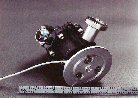
GP-B/STEP
proportional thruster
How is the
helium temperature regulated?
The temperature of the helium is determined by the pressure in the tank, which is in turn determined by the heat leak into the tank and the impedance of the vent line. The impedance of the vent line is controllable, and set by all of the helium thrusters. By throttling the vent line we can change the tank pressure and so control the temperature. In normal operation the helium boiloff exceeds the amount of gas needed to cancel drag, and the excess is null-dumped, meaning that equal amounts are vented in opposite directions so as to produce no thrust. The excess can be throttled independently of the thrust produced by the gas, and this is what regulates the temperature.
What if STEP
were hit by a micrometeoroid?
Actual micrometeoroids are rare enough that we wont have to worry about them; the most likely particle impacts are from space debris, small particles from other satellites. In about 1990 we estimated that STEP might expect one or two impacts large enough to cause accelerometer saturation, in the six month mission. The consequence of such an impact is that we might have to cut out a section of data (a few minutes worth) around the time of impact; thats not too bad. Much larger impacts, such as might cause the masses to contact the walls, would very likely damage the satellite. There could be a lot of smaller impacts, but so long as the accelerometers remain unsaturated there is little impact on the data.
Why doesnt
the drag free control cause the helium to slosh?
The drag free control actually prevents the helium sloshing. It causes the satellite to follow an inertial trajectory in spite of disturbances, that is, the same trajectory that it would follow if there were no disturbances at all. The helium, contained in the satellite, also follows the trajectory it would follow without disturbances. If something caused the helium to slosh, the helium moving back and forth would push against the satellite and disturb it. The drag free control would react to this disturbance by preventing the satellite from moving. Since the feedback is stable, this always reduces the heliums motion.
What is the
helium tide?
What is an ordinary tide? It is sloshing of the oceans in response to the changing gravity gradient of the moon. A similar thing can happen to superfluid helium in the STEP dewar. Although it is a lot smaller than an ocean, the helium is excited by the Earths gravity gradient, which is a lot stronger than the moons, and theres not much holding it in place (like gravity holds the oceans). The tide on the helium constitutes a moving mass which couples gravitationally to the accelerometers. This effect occurs at a multiple of the signal frequency, and since there are a lot of things going on that could convert part of it to the signal frequency, theres been a lot of fuss and bother about how big a problem it is for STEP,and what to do about it. The fact that the helium is superfluid, and has no significant viscosity or damping, merely adds to the concern.
As background, a few simple cases can be calculated. Its not too hard to figure out the equilibrium shape of a free-floating droplet of helium distorted by the Earths gravity gradient. Its a balance between the surface energy (surface tension) and the potential energy of the material in the gradient. A droplet nominally 70 cm in radius would distort about 10 cm, but a 40 cm drop would distort only about a centimeter. The smaller drop is stiffer and the gravity gradient force on it is weaker. The actual dynamic case is much more difficult, but youd expect the amplitudes to be similar. This suggests that we are right to be concerned about helium tides; they might cause a disturbance more than several hundred times our desired sensitivity.
The helium is actually contained in a toroidal tank in the dewar. The constraint brings in a number called the capillary length which measures the ratio of surface tension to gravity forces; in orbit, this is very large, tens of meters, so the shape of the helium surface is determined by capillary forces, even in a 1-meter sized chamber. In the toroidal case the shape of the free surface is not only hard to calculate; there are a lot of modes or resonant conditions that can be excited, corresponding to waves running around the toroid in different ways. The frequencies of these modes depend on the amount of free surface and its configuration. Since the helium is continually boiling away, the expectation is that the state of the helium tide would be continually changing.
The superfluid properties of helium are also a concern since it appears at first that excitations of the fluid will not die out. This turns out to be incorrect for motions the size that we are concerned with. Fluid motion is converted into internal vorticity at a rate consistent with the normal viscosity.
How is the
helium tide controlled?
A number of schemes have been suggested for controlling the helium tide. Electrostriction, using an electric field to pull the helium into a stable configuration, fails because helium has a very small dielectric constant and very large voltages would be needed to produce much force; more voltage than the helium gas might be expected to sustain. Surface tension is more hopeful, since the tidal amplitude decreases dramatically with the size of the fluid surface. One could envision containing the helium in many separate small chambers, each with a very stiff surface. But the chambers must be truly independent, otherwise they will be connected by superfluid and act more like a single large chamber; and that is very expensive.
The solution, which will be confirmed before flight by experiment, is to trap the helium in a substance called silica aerogel. This is neat stuff: it is silicafused quartz, basicallymade into a sort of foam until it is 90-99% empty space. The pores are microscopic, and except for some scattering the material is transparent and looks like a rigid cloud of smokesee the picture. It has some slightly weird properties which dont directly concern STEP. The idea is that the helium will be wicked into the pores by a combination of surface tension and Van der Waals force. These forces are so much stronger than gravity, on the scale of the pores, that the small gravity gradients can have no perceptible influence. The other photograph shows a sample of aerogel, in which superfluid helium (the light area) is suspended in 1 g at the top of the sample. If helium can be so rigidly suspended in 1 g, how far will it move due the million times smaller gravity gradient forces in orbit?